

Description
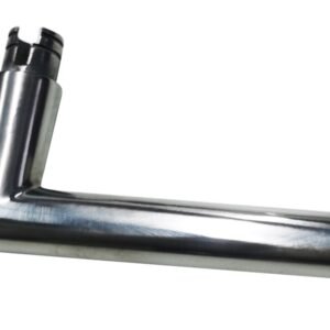
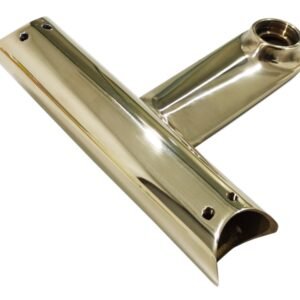
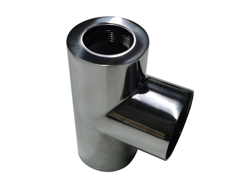
A stainless steel angle valve body can combine a curved outer shell, short branches, shoulders and threaded connections. These features need different polishing positions, while the fixture must hold the part without marking the visible surface. Kingstone configures CNC polishing around the geometry of the valve body and the surfaces identified on your drawing.
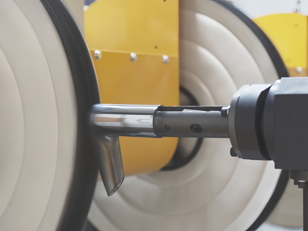
The application described here concerns external appearance finishing. Threaded connections, sealing faces, internal passages and other functional areas are identified separately during process planning so their dimensions and condition can be preserved.
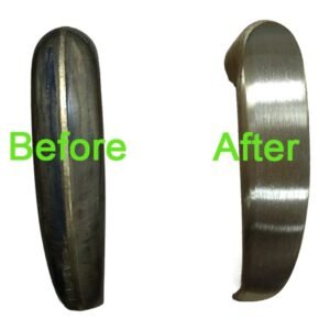
Define the incoming surface and final appearance
Start with a representative valve body, its material grade and the surface condition after casting, forging or machining. A cloth wheel polishing operation may need earlier grinding or sanding when the part has deep scratches, a pronounced parting line or uneven stock. The preparation sequence is selected from sample trials rather than from the finished appearance alone.
For a bright or mirror appearance, agree on a physical reference sample and inspection conditions. Where roughness is specified, also define the measurement location and method. A roughness value and a visual standard describe different aspects of the result and should both be recorded when relevant.
Fixtures for the valve body
The fixture is designed around stable locating features, clear wheel access and the loading orientation. Its contact surfaces must suit the part material and the cosmetic requirements. The setup should provide repeatable positioning while keeping specified threads, sealing faces and mounting features outside the polishing contact area.
During evaluation, we check access to the elbow, branch transitions and shoulders. A narrow recess or an area blocked by the fixture may require a different wheel, a revised holding position or a separate operation.
Polishing sequence and process control
- Load and locate the valve body in the agreed fixture.
- Run the stored CNC program for that part reference.
- Present the selected outer surfaces to the cloth wheels using the validated motion sequence.
- Apply solid polishing compound at the programmed intervals.
- Unload, clean as required and inspect the agreed appearance and protected features.
Wheel selection, contact conditions, compound feeding and the starting surface all affect the result. The final cycle time is established with the complete sequence, including loading, repositioning and normal consumable interventions.
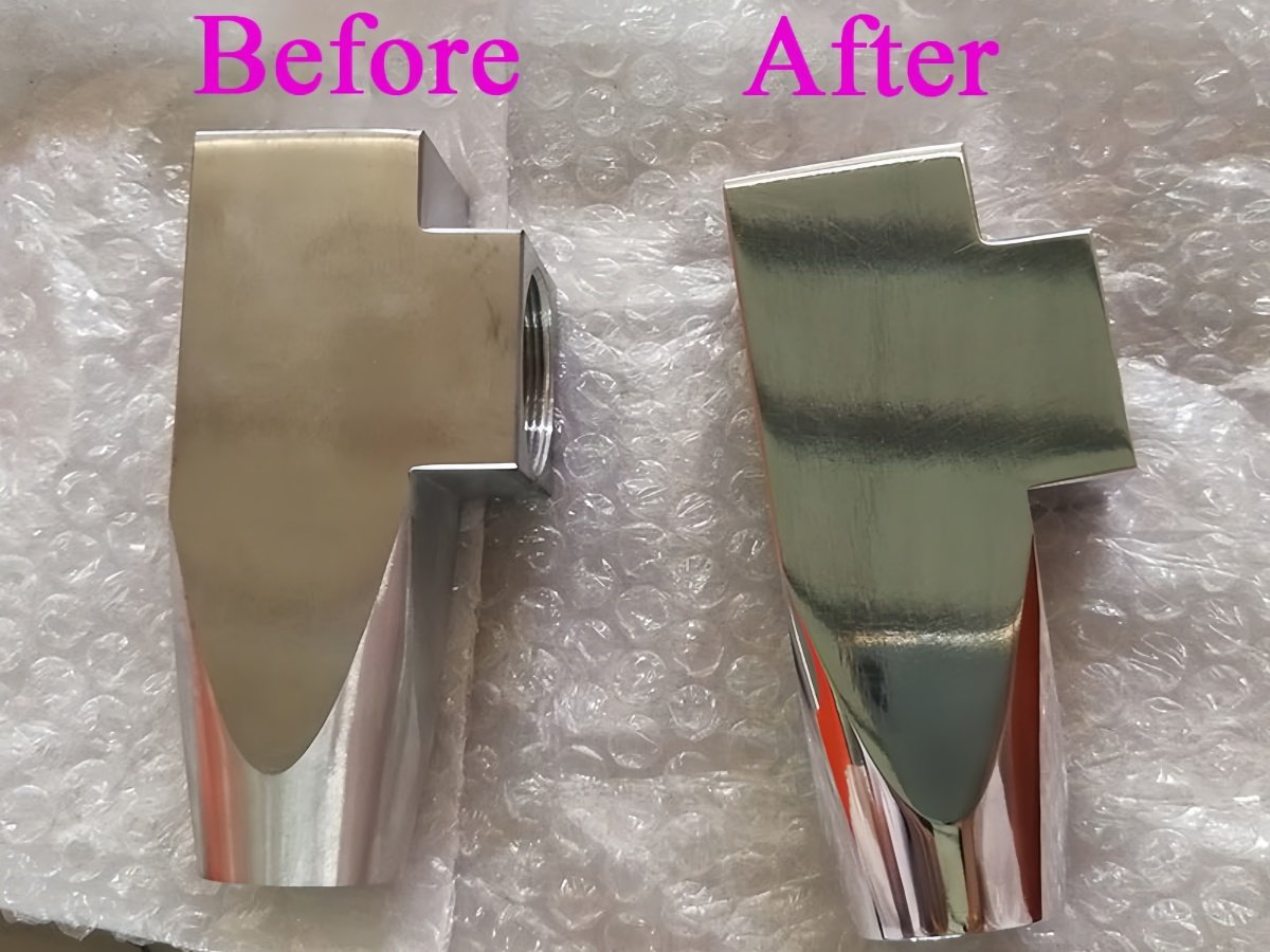
Reference machine configuration
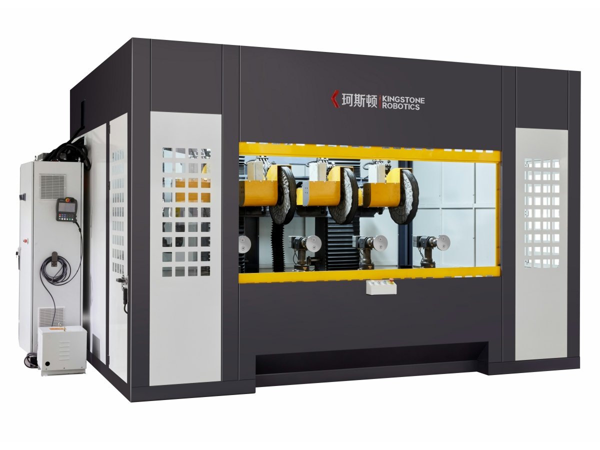
The following configuration is the reference equipment described for this application. The selected machine and fixture arrangement are confirmed for the actual valve body before an order is finalized.
| Item | Reference configuration |
| Machine type | CNC cloth wheel polishing machine |
| Workstations | 4 |
| Polishing heads | 4 |
| Control and servo system | HUST |
| Polishing media | Cloth wheels and solid polishing compound |
| Compound application | Automatic feeding with programmable timing |
| Program operation | Teaching and stored program recall |
For a broader comparison of machine layouts, see our CNC polishing machines. Related workpieces are covered in our bathroom hardware finishing applications.
Information for an application review
- Part drawing or 3D model, material grade and representative samples.
- Marked surfaces to polish and features to protect.
- Photos of the incoming surface and the accepted finished sample.
- Required output, part variants, loading method and available floor space.
- Site utilities and the extraction arrangement for the polishing process.
Frequently asked questions
Can one machine process different angle valve bodies
Compatible part families may share a machine with dedicated fixtures and programs. Compatibility depends on access, size, locating features and the required polishing sequence. Each proposed variant should be included in the application review.
Does cloth wheel polishing remove casting defects
The operation is evaluated against the starting surface. Deeper defects or heavy excess material may require an earlier material removal step before final polishing.
How is the final finish confirmed
Use an agreed sample and written inspection requirements. If a numerical surface requirement is specified, the trial should use the same measurement method intended for production acceptance.
Discuss your angle valve polishing application
Send your angle valve drawing and surface photos for a review of the fixture, process sequence and suitable machine configuration.