Automated Deburring for Metal Parts

Kingstone Robotics designs robotic deburring cells to remove burrs, casting flash and unwanted sharp edges from metal components. The robot, tooling, fixture and handling sequence are selected around your part geometry, material, incoming condition and required edge quality. Representative sample testing helps define the process and achievable result.

Robotic Deburring Applications

Parts and Features We Evaluate

Robotic deburring can be evaluated for housings, brackets, cast components and automotive parts. The suitable method depends on burr location, material, tool access and the edge condition required after processing.

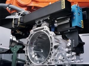
Robot-mounted tool processing the edge of a metal housing

Housing Edge Deburring

Remove burrs around accessible openings, flanges and external edges while protecting the surfaces and dimensions identified in the part drawing.
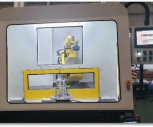
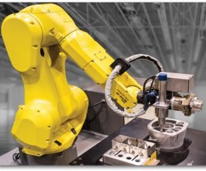
Enclosed robotic processing cell for metal components

Small-Part Deburring

Evaluate local burr removal on compact metal components using a suitable fixture, deburring tool and defined loading position.
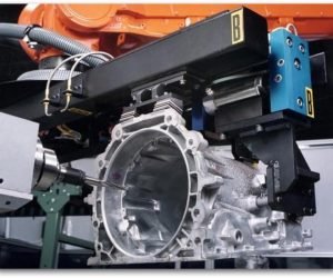
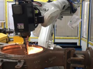
Deburring equipment working on a cast metal housing

Cast Housing Deburring

Develop a process for accessible casting flash and unwanted edge material, with tool clearance and allowable material removal checked on actual samples.
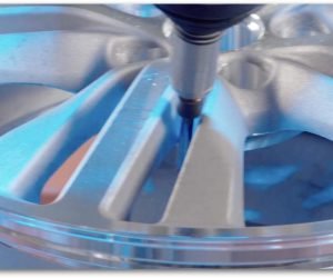
Cutting tool processing a feature on an automotive wheel

Automotive Wheel Deburring

Assess burr removal on specified wheel features and accessible edges, with the finished condition agreed before process development.

Configure the Deburring Cell Around Your Part

The cell layout and tooling are developed from the workpiece and finishing task. The following elements can be considered during application review; the final equipment scope is defined in the project proposal.

Burr and Flash Removal

Define the areas to process, the incoming burr condition and the amount of material that may be removed before selecting the tooling.

Deburring Tool Selection

Suitable tools may include rotary cutters, abrasive belts, wheels or brushes. The tool type and process sequence are assessed with representative parts.

Workpiece Holding

Grippers and fixtures locate the component securely and provide access to the required processing areas. Supports are reviewed where the workpiece can deflect.

Contact Control

Mechanical compliance or force control may help manage contact variation within the tested process range. The required method depends on the tool and workpiece.

Loading and Unloading

Manual loading, trays, indexing tables or conveyor handling can be considered according to part presentation, production volume and the intended operating sequence.

Multiple Process Stations

More than one tool or abrasive stage may be needed for flash removal, blending and edge finishing. Each stage is evaluated against the required result.

Position and Inspection Options

Part-presence checks, position verification or vision may be considered where needed. Inspection requirements and equipment are specified for the actual application.

Guarding and Debris Management

Plan guarding, chip or dust management and maintenance access around the selected process, workpiece material and operating layout.

Typical Deburring Tasks

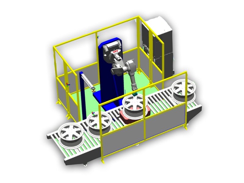
Concept layout of a robotic wheel deburring cell with a conveyor

Concept Layout: Conveyor-Fed Wheel Deburring Cell

Illustrated arrangement combining wheel presentation, robot processing and a guarded working area. Tooling, locating and handling details are developed for the actual wheel and deburring task.
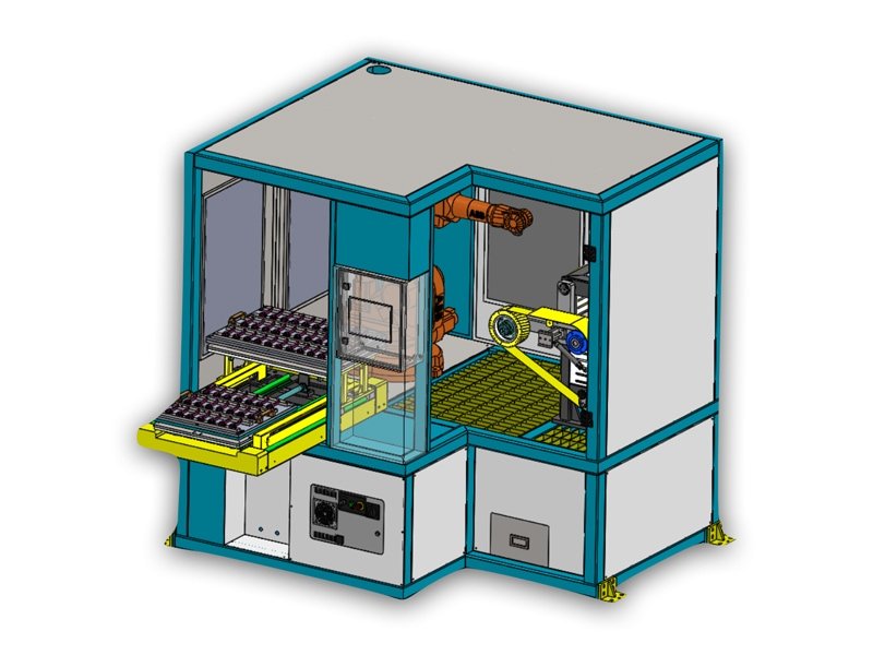
Concept layout of an enclosed robotic finishing cell with loading trays

Concept Layout: Enclosed Cell With Tray Loading

Illustrated cell with a tray-loading arrangement and enclosed abrasive processing area. The finishing stations, gripper and process sequence are selected after the part review.
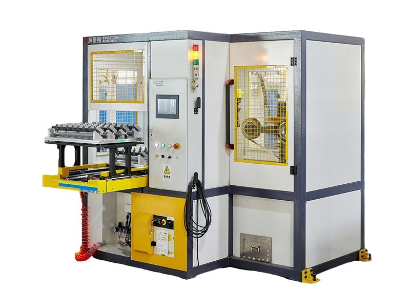
Enclosed robotic finishing machine with a part-loading table

Enclosed Robotic Finishing Cell

Machine example with a part-loading table and guarded processing area. Application-specific fixtures and tools define which grinding and deburring tasks the cell performs.

Application Engineering for Robotic Deburring

  • Workpiece review before the cell configuration is finalized
  • Sample testing to develop the tool and process sequence
  • Fixture and gripper design around the required processing areas
  • Defined edge-quality and dimensional acceptance criteria
  • Operator training and support for routine operation and maintenance

Start With Your Part and Burr Condition

Send us clear photos of the raw part, marked burr locations, a drawing and your required finished edge. We can review tool access, holding options and the process testing needed for your application.

Four Challenges in Robotic Deburring


Incoming-part variation, tool wear, part changeover and finished edge quality all affect the deburring process. These factors should be evaluated during sample testing and cell design.

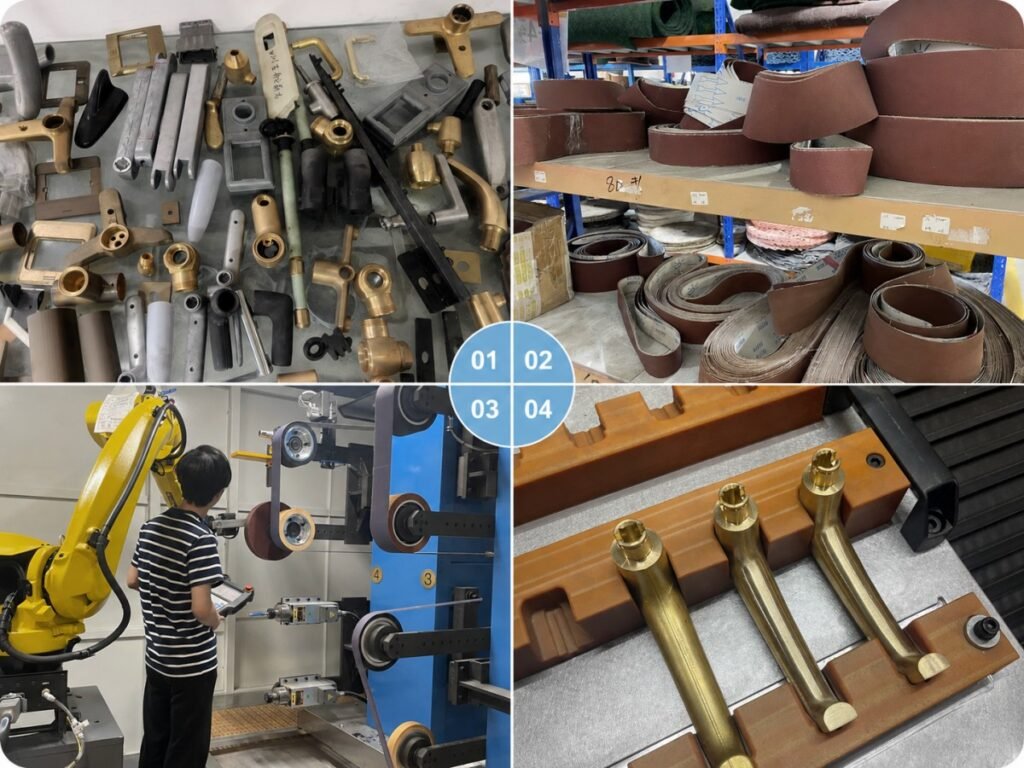
01. Incoming-Part Variation

Burr size, casting condition and part position can vary. Representative samples help define the incoming range the proposed process needs to handle.

03. Part Changeover

Different models may require different fixtures, tool data or programs. Confirm each approved setup and include changeover work in production planning.

Incoming parts, abrasive belts, robot programming and finished-part quality

02. Tools and Wear

Tool choice and wear affect material removal and edge quality. Establish the suitable sequence, inspection points and replacement or compensation approach during testing.

04. Finished Edge Quality

Agree the allowed burr condition, protected features and relevant dimensional checks. Evaluate repeated samples against the same acceptance criteria.

From Sample Testing to Production

Step 1: Part and Process Review

Share the material, geometry, weight, burr locations, current process, target edge quality and production requirements.

Step 2: Sample Deburring

Test representative parts to evaluate the tool, contact method, access, material removal and achievable finished condition.

Step 3: Cell and Tooling Design

Develop the robot configuration, fixtures, handling sequence, processing stations and guarding around the reviewed application.

Step 4: Factory Testing

Run the agreed parts and operating sequence on the completed cell. Check the finished result, handling and cycle performance against the acceptance plan.

Step 5: Installation and Training

Confirm installation and commissioning arrangements and train the customer’s team on setup, operation, changeover and routine maintenance.

Step 6: After-Sales Support

Provide operating guidance, service assistance and spare-parts support according to the agreed project scope.

Benefits of a Validated Deburring Process

  • More repeatable processing under defined tooling and operating conditions
  • Reduced dependence on repetitive manual burr removal
  • A clearer basis for cycle-time and production planning
  • Controlled handling and access to the agreed processing areas
  • Documented setups for repeat production of approved part models

Discuss Your Robotic Deburring Project

Share your part photos or drawings, material, dimensions, burr locations, target edge quality and required output. Representative samples help us evaluate the process and recommend a suitable robotic deburring configuration.

  • Raw-part photos or a drawing with burr locations marked
  • Material, dimensions and workpiece weight
  • Accepted finished edge and protected surfaces
  • Required good parts per shift and product mix
Blank Form (#3)