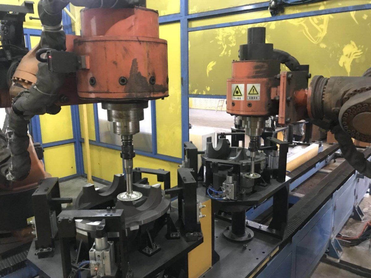
Description
Gearbox Housing Grinding and Deburring Applications
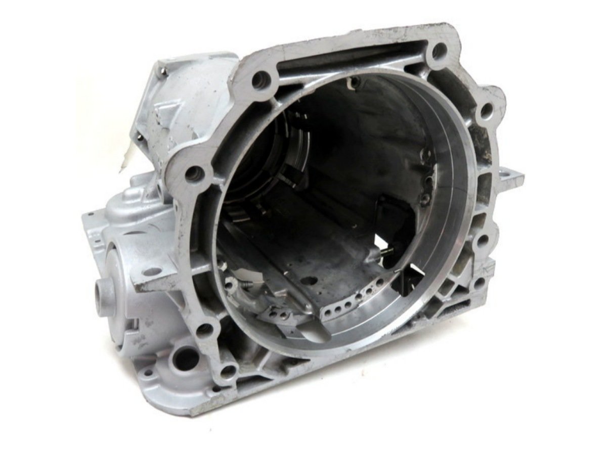
Gearbox housings can retain casting flash, raised parting lines, gate or trimming remnants, sharp edges and burrs created by drilling or machining. Their ribs, bosses, flanges, ports, cavities and machined features can make manual processing difficult to standardize.
Kingstone develops robotic grinding and deburring cells around the actual housing, defect locations and acceptance standard. The process is designed to remove material only from approved areas while avoiding sealing faces, bearing seats, threaded holes, mounting datums and other critical features.
Typical processing tasks include:
- Removing casting flash and raised material along approved parting lines.
- Reducing gate or trimming remnants where material removal is permitted.
- Removing sharp edges from external contours and accessible openings.
- Deburring drilled or machined holes, ports and intersecting features.
- Removing local excess material that may interfere with handling or assembly.
- Blending approved non-critical areas after heavier stock removal.
Grinding and deburring are treated as separate operations. Grinding normally removes heavier excess material, while deburring targets smaller burrs and sharp edges. Cosmetic polishing or a specified surface finish is not included unless it is separately defined and validated.
For the broader equipment platform, see our robotic grinding workstation and robotic deburring machine.
Two Robotic Processing Layouts
The system layout is selected from the actual workpiece, not from a fixed machine specification.
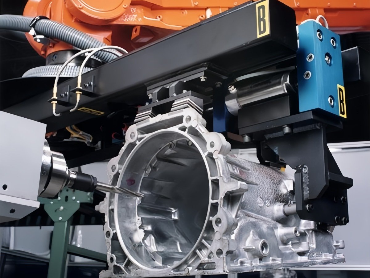
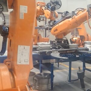
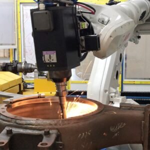
Robot-Held Tool for a Fixed Gearbox Housing
For a large, heavy or awkward housing, the component is normally secured in a custom fixture while the robot carries the grinding or deburring tool. This layout limits the load moved by the robot and can provide flexible access around the fixed part.
It is commonly evaluated when:
- The housing and gripper would create a high combined payload.
- The part has an offset center of gravity or high inertia.
- Several local areas require different tool orientations.
- The workpiece needs strong support during material removal.
- Loading the housing into a repeatable fixture is practical.
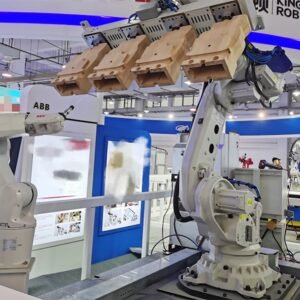
Robot-Held Workpiece with Fixed Process Equipment
For a smaller housing, the robot may grip the workpiece and present it to a stationary belt grinder, wheel or other process station. This arrangement can be suitable when the gripper can expose every approved processing area and the combined workpiece-and-gripper load remains within the robot’s dynamic limits.
It is commonly evaluated when:
- The workpiece is suitable for stable robotic gripping.
- Multiple edges can be presented efficiently to a fixed tool.
- The robot has sufficient payload, reach and wrist capacity.
- The process station can provide the required contact condition.
The final decision must consider total payload, center of gravity, inertia, robot reach, collision clearance, fixture or gripper repeatability, process force, tool changes and cycle time. Read our comparison of robot-held parts and robot-held tools for more detail.
Typical System Configuration
A project-specific gearbox housing grinding and deburring cell may include:
- A six-axis industrial robot selected for the required payload, reach and process load.
- A custom fixture, gripper or positioner designed around stable part datums.
- Belt grinding, rotary deburring or other tools validated during trials.
- Compliance or force-control equipment where controlled contact is required.
- Automatic tool changing, tool measurement or abrasive-wear compensation where justified.
- Manual loading, an indexed table or automated loading and unloading.
- PLC control, recipe selection and production status monitoring.
- Safety guarding, access interlocks and an emergency-stop system.
- Dust or chip extraction designed for the workpiece material and selected process.
| Item | Project-Specific Configuration |
|---|---|
| Application | Casting flash, raised parting lines, gate or trimming remnants, sharp edges and machining burrs on approved areas |
| Workpiece | Gearbox housings and similar transmission casings |
| Materials | Aluminum alloy, cast iron or other metals confirmed through sample testing |
| System Layout | Robot-held tool or robot-held workpiece, selected according to part size, weight, geometry and access |
| Robot | ABB, FANUC or KUKA; payload and reach selected for the actual tool, workpiece and process load |
| Process Tools | Belt grinding, rotary deburring spindle, carbide burr, flap wheel or other validated tooling |
| Workholding | Custom fixture, gripper or positioner |
| Process Control | Programmed paths with optional compliance or force control, position checking and tool-wear compensation |
| Loading | Manual loading, indexed table or automated loading and unloading |
| Safety and Extraction | Guarding plus dust or chip extraction configured for the workpiece material and selected process |
| Cycle Time | Confirmed through representative sample trials; not estimated from robot speed alone |
Final equipment specifications are confirmed after part review and process trials. Not every project requires every module listed above.
These are available configuration elements, not a fixed package. Each project should include only the modules required for the approved process and production target. Learn more about our robotic finishing technology, including process planning, fixture design, force control and consumable management.
How the Robotic Process Works
1. Load and Locate the Housing
The operator, indexed table or automated handling system loads the housing into the fixture. The fixture locates the part from stable datums and supports it against the expected process forces.
2. Confirm Position When Required
If normal production variation can shift the target area, the cell may use a sensor, vision system or programmed checking routine. This function is selected only when the application requires it.
3. Remove Flash or Raised Parting Lines
The robot follows the approved grinding path using the selected abrasive and tested process parameters. Tool orientation, feed rate, contact condition and number of passes are established during sample trials.
4. Deburr Local Features
The robot changes tools or moves to a dedicated deburring station to process holes, ports, sharp edges and other approved local features. Each feature is programmed according to access and permitted material removal.
5. Manage Tool Wear
Abrasive wear changes the effective tool diameter and cutting behavior. Where required, the system can use tool-life tracking, measurement, programmed compensation or a controlled replacement interval.
6. Unload and Inspect
The processed housing is unloaded for the agreed inspection method. Inspection may be visual, tactile, dimensional or based on a customer-approved reference sample. Automated inspection is evaluated separately when the defect and acceptance criteria can be measured reliably.
Not every application requires all six stages. The production sequence is simplified wherever possible after the process has been validated.
Protecting Critical Features and Controlling Quality
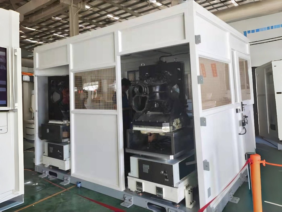
A gearbox housing may contain sealing faces, bearing bores, threaded holes, machined datums and dimensionally controlled surfaces. These features must be clearly marked as protected zones before process development begins.
Quality control can include:
- Repeatable part location from reliable datums.
- Defined processing and protected zones for every part model.
- Tool type, abrasive specification or cutter geometry selected through trials.
- Controlled spindle speed, robot speed, contact condition and number of passes.
- Tool-wear monitoring and a defined replacement method.
- Separate programs and recipes for different housing models.
- Inspection criteria linked to a drawing, measurable limit or approved sample.
Force control is not automatically required for every project. It may improve contact consistency where an acceptable level of part variation must be accommodated, while other operations may be better controlled through fixture accuracy, tool compliance or position checking.
If incoming part variation is wider than the process can safely absorb, the correct solution may involve upstream control, sensing or part sorting rather than more aggressive grinding. For related process guidance, see robotic grinding for cast metal parts.
Representative Sample Testing
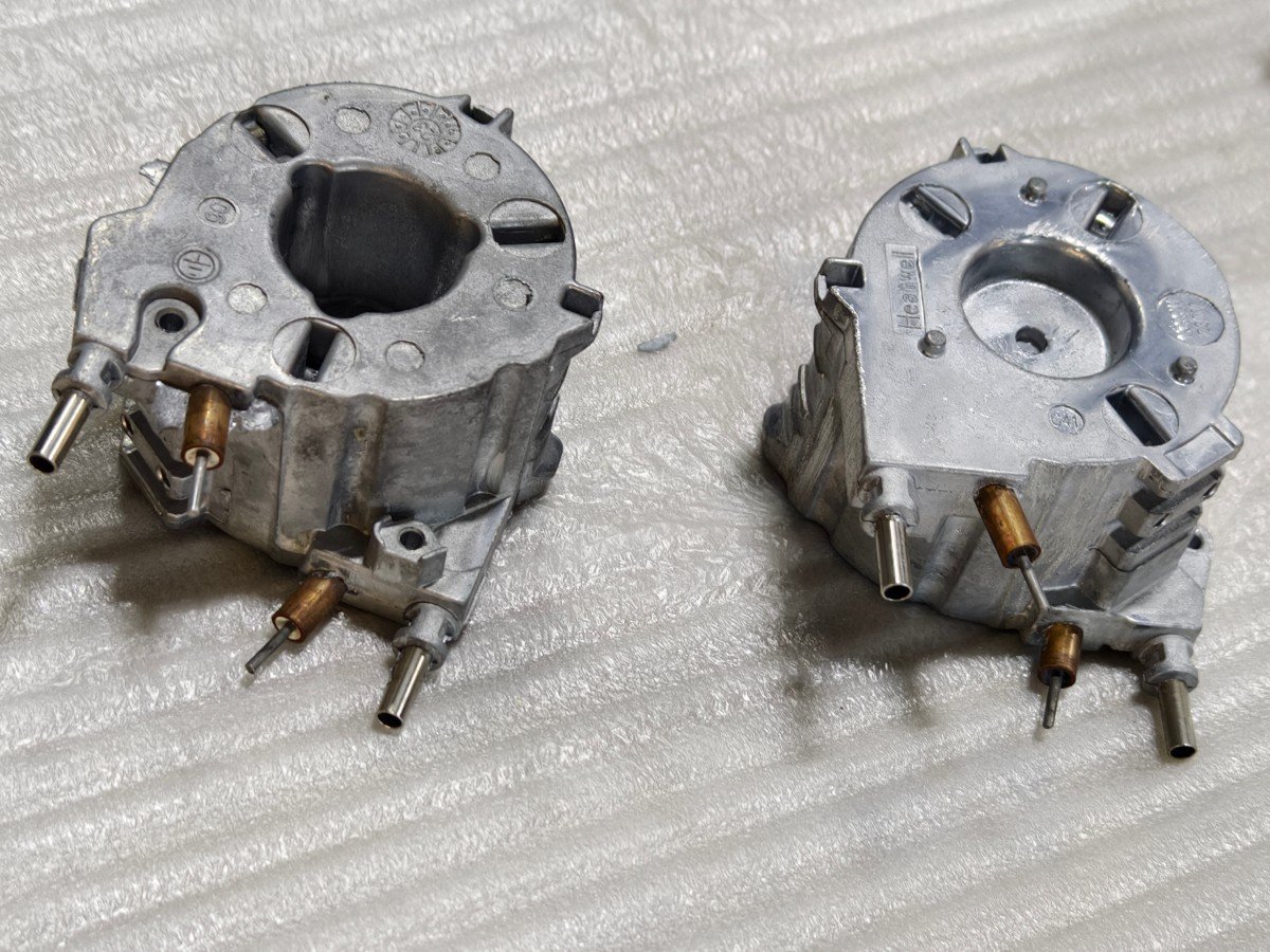
A trial based on one unusually clean or unusually rough housing does not represent normal production. Sample testing should use several parts covering the expected range of flash, burr size, casting variation, machining variation and approved model differences.
Representative sample testing helps confirm:
- Whether all target features are accessible.
- Which grinding and deburring tools are suitable.
- The required process speed and number of passes.
- Whether compliance, force control or position checking is needed.
- Whether critical features can be protected reliably.
- Expected abrasive or cutter wear.
- A realistic cycle-time range for the agreed scope.
Cycle time is confirmed from the validated process, including robot motion, tool changes, loading, unloading and required inspection. It should not be estimated from robot speed alone.
Information Needed for a Proposal
To evaluate your gearbox housing application, please provide:
- Clear photographs, 2D drawings and an available 3D model.
- Workpiece material and manufacturing process.
- Overall dimensions and weight.
- Marked photographs or drawings showing every grinding and deburring area.
- Marked sealing faces, bearing locations, threads, datums and other protected areas.
- Representative raw parts covering normal production variation.
- An accepted finished sample or written inspection standard.
- Current manual tools and average processing time.
- Required parts per shift or annual production volume.
- Number of housing models and expected changeover frequency.
- Preferred loading method and available floor space.
- Relevant washing, inspection or downstream assembly requirements.
Providing these details at the beginning reduces assumptions and allows the trial plan, equipment concept and quotation to be based on the real production requirement.
From Sample Testing to Production
1. Application Review
We review the workpiece, defect locations, protected features, current process, part variants and production target.
2. Representative Sample Trials
Relevant tools and parameters are tested on actual parts. The processed samples are reviewed against the agreed acceptance standard.
3. Cell and Fixture Design
After the process route is confirmed, the robot, tools, workholding, loading method, extraction, safety system and cell layout can be specified.
4. Manufacturing, Programming and Acceptance
The system is assembled and programmed around the approved scope. Factory acceptance criteria cover the selected part models, processing areas, quality requirements and production sequence.
5. Installation, Training and Support
Installation, operator training, maintenance instructions and production support are planned according to the project location and contract scope. See our custom automation services for the wider project workflow.
Frequently Asked Questions
Can the system process both cast aluminum and cast iron gearbox housings?
Both materials can be evaluated, but they do not automatically use the same abrasive, tool, speed, extraction method or process parameters. The final configuration must be established through testing with the actual material and defect condition.
Can one robotic cell perform both grinding and deburring?
Yes. A cell can include separate tools or process stations for heavier grinding and localized deburring. The best layout depends on access, required material removal, tool-change time and the production target.
Can one cell process several gearbox housing models?
It may be possible to use multiple fixtures, adjustable workholding, stored programs and separate tool recipes. Each model still needs its own reach, collision, process and quality validation.
How are sealing faces and bearing seats protected?
Critical features are identified as protected zones before programming. Controlled approach directions, fixtures, physical protection where practical and validated tool paths may be used. The approved sample and inspection plan must confirm that these surfaces remain within requirement.
Is force control always required?
No. Force control or compliant tooling can be useful when controlled contact must accommodate an acceptable amount of variation. Other operations may be better controlled by fixture accuracy, tool compliance, position checking or a combination of methods.
What determines the cycle time?
Cycle time depends on the number and size of defects, workpiece material, permitted removal rate, tool selection, number of passes, robot access, tool changes, loading, unloading and inspection. A reliable value comes from representative sample trials.
Is automatic loading available?
Automatic loading and unloading can be evaluated. Manual loading or an indexed table may be more practical for lower production volumes, frequent model changes or heavy components.
Why are representative sample parts necessary?
Drawings and photographs cannot show the complete range of burr height, flash thickness, local hardness, casting variation or tool wear. Representative parts allow the process window and realistic cycle time to be validated before the equipment design is finalized.
Does this system polish the complete gearbox housing?
Not unless polishing is separately defined and validated. Grinding removes heavier excess material, while deburring removes sharp edges and localized burrs. Cosmetic polishing or a specified surface finish may require different tools and process stages.
Send Your Gearbox Housing for Evaluation
The most reliable equipment concept begins with the actual part and a clear acceptance standard. Send us your drawings or 3D model, material, dimensions and weight, marked processing areas, protected features, representative raw parts and target production output.
Contact our engineering team to arrange an application review and representative sample test.