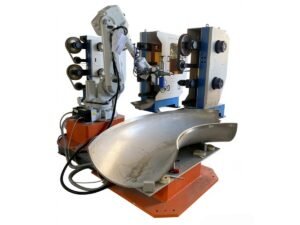
Kingstone Robotics integrates robots, process tools, fixtures and controls into custom finishing cells for complex components. Each system is planned around the workpiece material, geometry and areas to process.
Grinding, deburring and polishing stages are selected to suit the required result. Tool changing, part positioning, loading and extraction arrangements are defined in the application proposal.
Complex castings and fabricated components can require different tools for different surfaces. We review the areas to process, the material to remove and the features to protect before selecting a cell concept.
• Workpiece material, dimensions and weight.
• Incoming surface condition and target processing areas.
• Tool access, workholding and locating surfaces.
• Loading, positioning and part transfer requirements.
• Required result and inspection criteria.

The final equipment specification is defined for each application. The options below are selected to suit the workpiece, process and production requirements.
Loading arrangements are planned around part weight, operator access and the production flow. Manual loading, transfer devices or linked equipment are specified in the project proposal.
The tool storage arrangement provides defined locations for the tools used in the process. Tool identification and access requirements are considered during cell design.
Locating fixtures establish how the workpiece is positioned. Where an additional locating system is specified, its purpose, working range and limitations are defined for the application.
Tool contact is managed through the selected tooling, robot program and workholding arrangement. Force control is included where required and specified in the project scope.
Fixtures and positioning equipment are selected to give the tool access to the required surfaces. The loading and processing sequence is checked during cell planning.
Tool changing can be included when the process uses several tools. Automatic tool changing and abrasive replacement are treated separately in the equipment specification.
Any specified sensing is defined by the feature to be checked and the required tolerance. Process checks are distinguished from final part inspection.
The cell design considers access guarding, material containment and extraction connections. The enclosure and collection equipment are selected for the material and finishing process.
These images show reference layouts and equipment arrangements. The final cell configuration is developed for the workpiece and project scope.
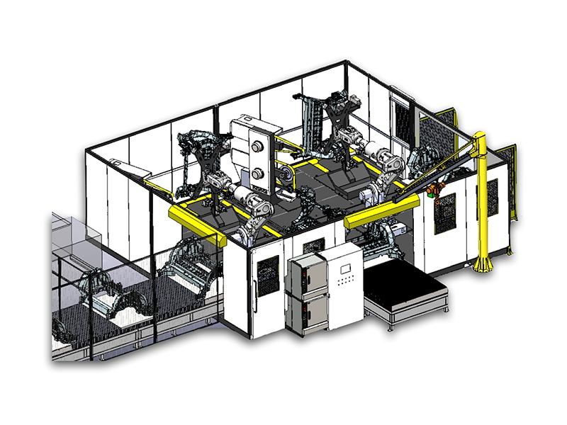
Reference layout showing how processing and part handling can be arranged within a robotic cell.

Example arrangement with a process enclosure and a defined part transfer route. Access and extraction requirements are specified for each project.

Reference workstation for reviewing the layout and enclosure of a large casting grinding application. Workpiece capacity is confirmed during project planning.
Send a drawing or clear photographs of the workpiece, together with its material, incoming condition and required result. We will review the application before proposing a cell configuration.
Representative parts are reviewed to understand variation in the starting surface and stock to remove. The process plan identifies the limits that tooling, fixtures and any specified sensing must accommodate.
The fixture arrangement and robot path are developed around the surfaces to process and features to protect. Access to recessed areas is reviewed with the actual part geometry.
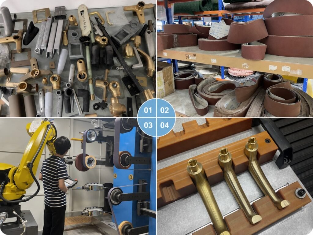
Tools and abrasive grades are selected for the material and required result. Replacement access, wear checks and consumable change procedures are considered in the cell design.
Representative sample parts are used to check tool access, material removal and the finished result. Acceptance criteria are agreed for the application, including the areas to process, features to protect and inspection method.
Share the drawing or 3D model, material, workpiece dimensions and finishing requirements. We review the surfaces to process and the features that must remain protected.
The proposed process identifies tools, fixtures, workpiece positioning, loading and the overall layout. Required options and acceptance criteria are recorded in the project scope.
The agreed cell is assembled with the selected robot, process tools, fixtures and controls. Programs are developed for the specified part references and processing stages.
Representative parts are used to check tool access, material removal and the finished result against the agreed acceptance criteria. Processing time is reviewed under the specified test conditions.
Installation and commissioning are arranged within the agreed scope. Training covers operation, approved changeovers, consumable replacement and routine equipment checks.
Support is based on the delivered system and agreed service terms. Machine identification, alarms and photographs or video help the team review a service request.
The project agreement defines the service scope and warranty terms for the delivered system.
To review your application, please prepare the following information. The equipment proposal will define the selected robot, process tools, fixtures, loading arrangement and service scope.
• Component drawing or 3D model.
• Material, dimensions and part weight.
• Photographs of the incoming surface.
• Areas to process and features to protect.
• Required finish and inspection criteria.
• Target output and number of part variants.
• Available floor space, utilities and delivery location.
Tell us about the component and the result you need. Include its material, approximate dimensions, starting condition and target output.
For drawings or photographs, email info@automatedpolish.com.