Description
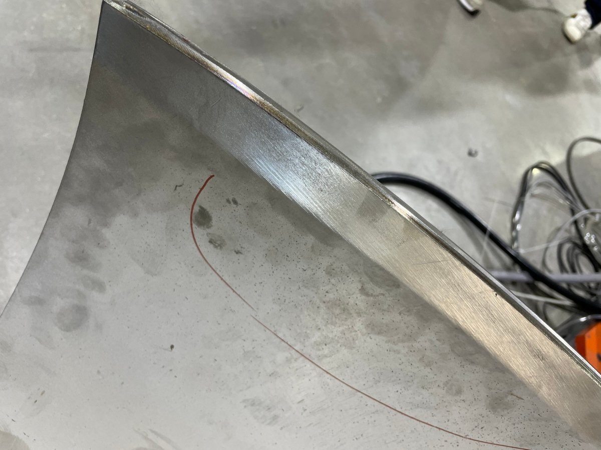
Finishing the edge of a pipe component requires control of the contact position as the surface curves around the part. The suitable process depends on the pipe geometry, wall condition, incoming edge and final appearance. Kingstone develops the grinding and polishing sequence around these features and the surfaces marked on the drawing.
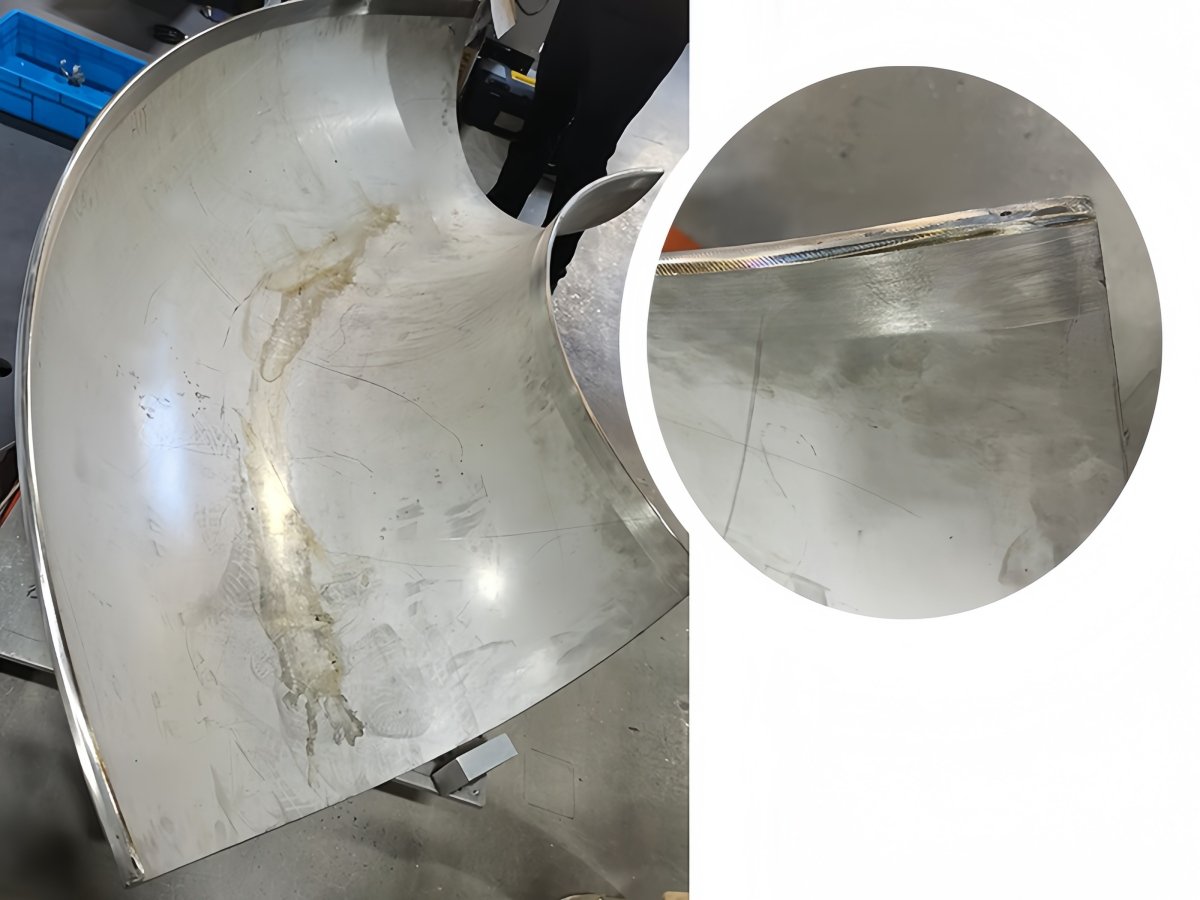
This application covers accessible pipe edges. Pipe outside diameter finishing, long tube centerless polishing, internal bore finishing and weld preparation have different process requirements and are assessed separately when requested.
Specify the edge and the required result
Provide the pipe material, diameter, wall thickness, length and part weight, together with the manufacturing process that creates the edge. Mark the area requiring grinding or polishing and identify any edge geometry, coating preparation or appearance requirement.
Representative samples help establish how much material needs to be removed and how the condition varies across the batch. If a numerical finish or dimensional requirement applies, record the inspection location and method before selecting the abrasive stages.
Locate the pipe component consistently
The workholding review considers the locating features, rigidity and access around the edge. The fixture or gripper must support the component without unacceptable deformation or marking. The loading orientation should make the starting position repeatable.
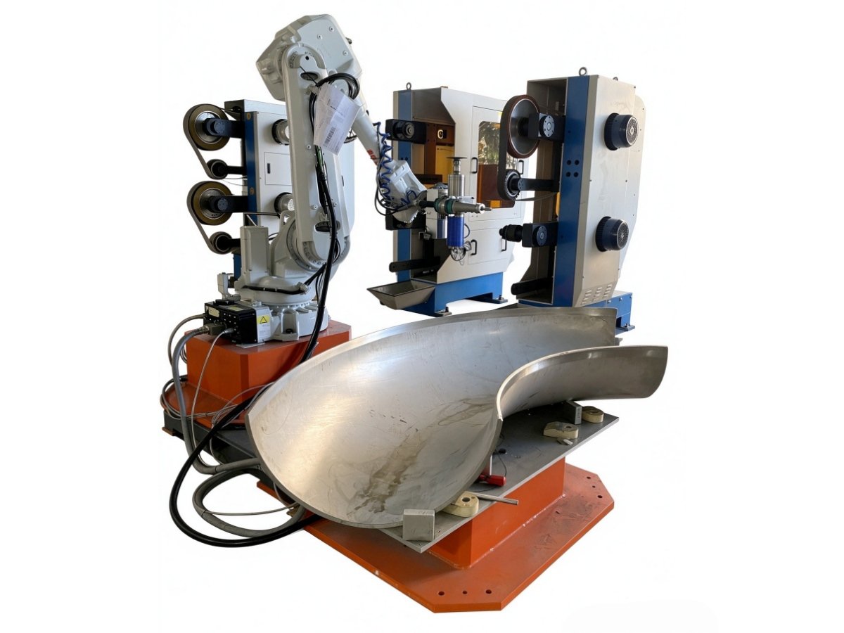
One layout presents the pipe component to fixed abrasive equipment. The suitability of this arrangement depends on the complete robot load, including the workpiece and gripper, as well as the path and contact forces. Alternative handling arrangements can be reviewed for parts that do not suit this layout.
Develop the abrasive sequence
- Load and locate the pipe component.
- Run the program for the selected part reference.
- Grind the specified edge using the validated abrasive sequence.
- Use further finishing stages where the required appearance calls for them.
- Unload and inspect the agreed edge and adjacent surfaces.
Abrasive grade, contact conditions and the number of passes are established with the actual material. Belt wear and incoming edge variation must be considered when defining the process. A polishing or buffing stage is included only when it is required by the approved finish.
Reference cell arrangement
The published reference layout uses the equipment below. It illustrates a possible arrangement rather than a processing envelope for every pipe component. Final robot selection, fixtures, tools and utilities are defined for the application.
| Item | Reference configuration |
| Robot | FANUC M-710iC/50E |
| Belt grinding machines | 2 machines with 3 belts each |
| Total abrasive belts | 6 |
| Reference belt length | 4000 mm |
| Loading table | Double position automatic loading table |
| Reference supply voltage | 380 V |
| Reference machine power | 20 kW |
| Other elements | PLC control and an enclosed process area |
For applications that combine multiple finishing stages, see our combined robotic finishing systems. Broader process options are described on the robotic grinding and polishing machine page.
Check capacity and acceptance together
A useful trial records the complete processing sequence, loading time, consumable condition and inspection result. This allows the proposed output to be assessed against the actual production flow. The finished edge should be compared with the agreed sample or drawing requirement at the same locations used for acceptance.
Frequently asked questions
What pipe diameters can be processed?
The usable range depends on geometry, weight, clamping, reach and tool access. Send the proposed diameter and length range so the cell can be assessed for those parts.
Can the same cell grind and polish?
A cell can be configured with the stages needed for the approved process. Tool count, abrasive selection and the required finish determine the arrangement.
Is internal pipe finishing included?
Internal surfaces are reviewed as a separate access and process requirement. The scope of this application is the accessible edge identified on the workpiece drawing.
Review your pipe edge finishing task
Send your pipe drawing and edge photographs with the material, part weight, target finish and required output.