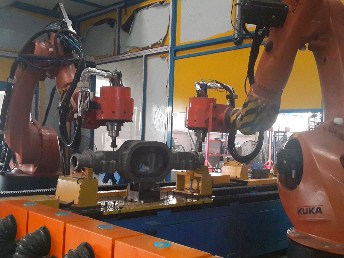
Description
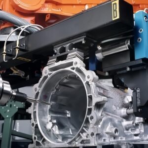
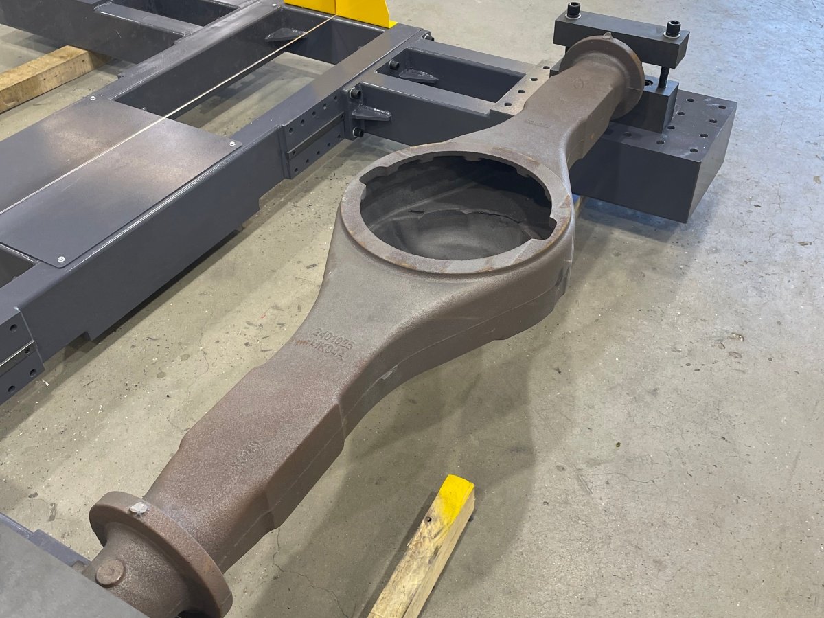
Cast drive axle components can carry flash, parting lines and local excess material that require different removal methods. Their weight and geometry also affect how the part is located and how the tool reaches each surface. A useful automation proposal therefore starts with the actual casting, its drawing and the condition in which it arrives at the deburring station.
Kingstone develops the cell around the specified workpiece. For an axle housing application, the review includes the larger outer surfaces, local transitions and functional features that need protection. Shafts, gears and other axle components require their own process assessment.
Identify the material to remove
Mark the parting lines, remaining gate or riser areas, edge burrs and local surface defects on the part drawing or photographs. Record the expected variation between castings. A cell designed for a light residual burr needs a different tool and load case from one intended to remove a larger casting remnant.
The review also identifies machined bores, bearing seats, sealing faces and datum surfaces. These features establish where material removal is permitted and where the process must preserve the existing geometry.
Select the handling and workholding arrangement
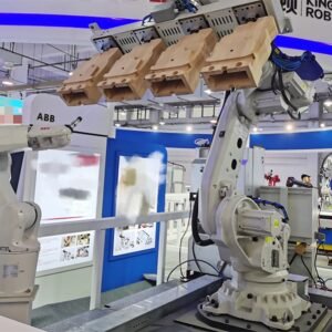
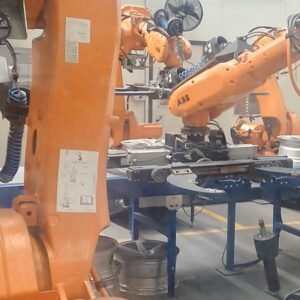
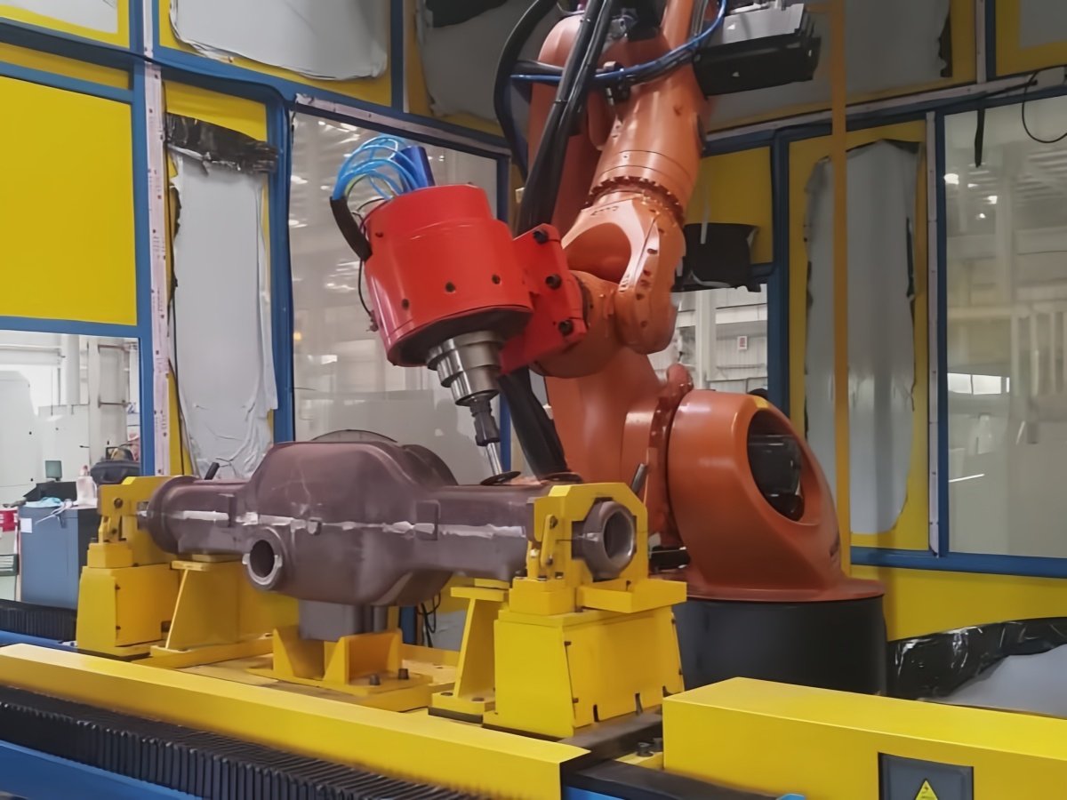
Two layouts can be considered. The robot may present a suitably sized component to fixed grinding or deburring tools, or it may carry a process tool around a component held in a fixture. Part mass, gripper mass, center of gravity, tool loads and access determine which arrangement is suitable.
For larger or less accessible workpieces, the review can include a positioner or an alternative fixture orientation. The loading method is selected with the production flow, available lifting equipment and operator access in mind.
Develop the grinding and deburring sequence
- Locate the casting using the agreed reference features.
- Check part seating and select the correct program.
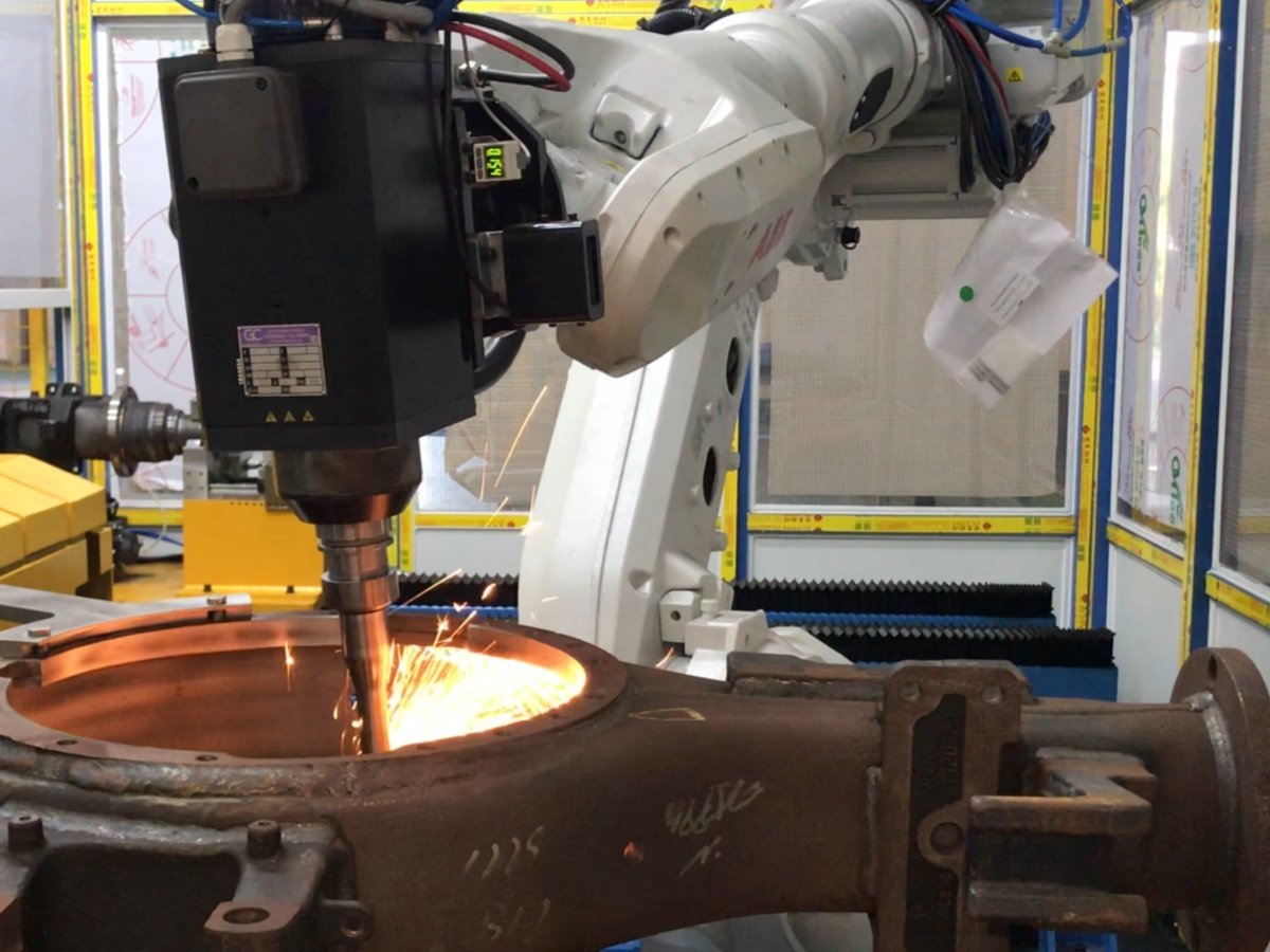
- Remove the specified excess material with the tools selected during trials.
- Reorient the part or change the tool where the process requires it.
- Inspect the critical removal areas and transfer the part to the next operation.
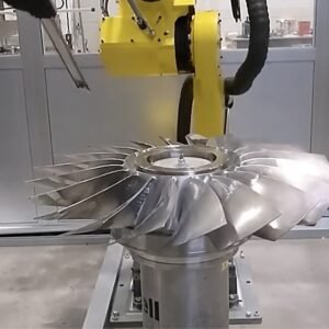
Potential tools include abrasive belts, grinding wheels and rotary deburring tools. The selection depends on the removal volume, access and permitted edge shape. Compliance, force control or part location sensing can be evaluated where casting variation justifies them.
Define the cell around production requirements
| Cell element | Selection basis |
| Robot and mounting | Reach, orientation, complete load case and process forces |
| Fixture or gripper | Part datums, casting variation and protected features |
| Process tools | Removal volume, surface access and tool life |
| Part loading | Batch size, part weight and upstream handling |
| Chip and dust management | Material, process debris and site extraction requirements |
| Program and inspection | Part variants and agreed acceptance criteria |
Agree on measurable acceptance criteria
The trial should use representative castings, including expected variation. Acceptance may cover remaining burr size, permitted edge geometry, protection of functional surfaces and the complete cell cycle. Define the inspection locations and method before evaluating the result.
A production cycle should include loading, positioning, processing and unloading. Tool changes, cleaning, planned maintenance and changeovers also need to be reflected in the capacity calculation.
See our robotic deburring systems for equipment options and our automotive component applications for related finishing tasks. Cast engine housings are addressed in a separate engine housing deburring application.
Frequently asked questions
Can the cell handle different drive axle castings?
A compatible part family may use different fixtures, grippers or programs in one cell. The range is confirmed by checking access, load conditions and the required tool sequence for each variant.
Can the system correct every casting defect?
The agreed process covers specified removal operations. Defects such as porosity, major dimensional errors or material damage need their own quality disposition.
What information is needed for a proposal?
Provide drawings, casting material, dimensions, weight, photos of the removal areas, expected casting variation, target output and your inspection requirements.
Review your drive axle casting
Send the drawing and marked removal areas so we can assess workholding, tool access and the proposed cell sequence.