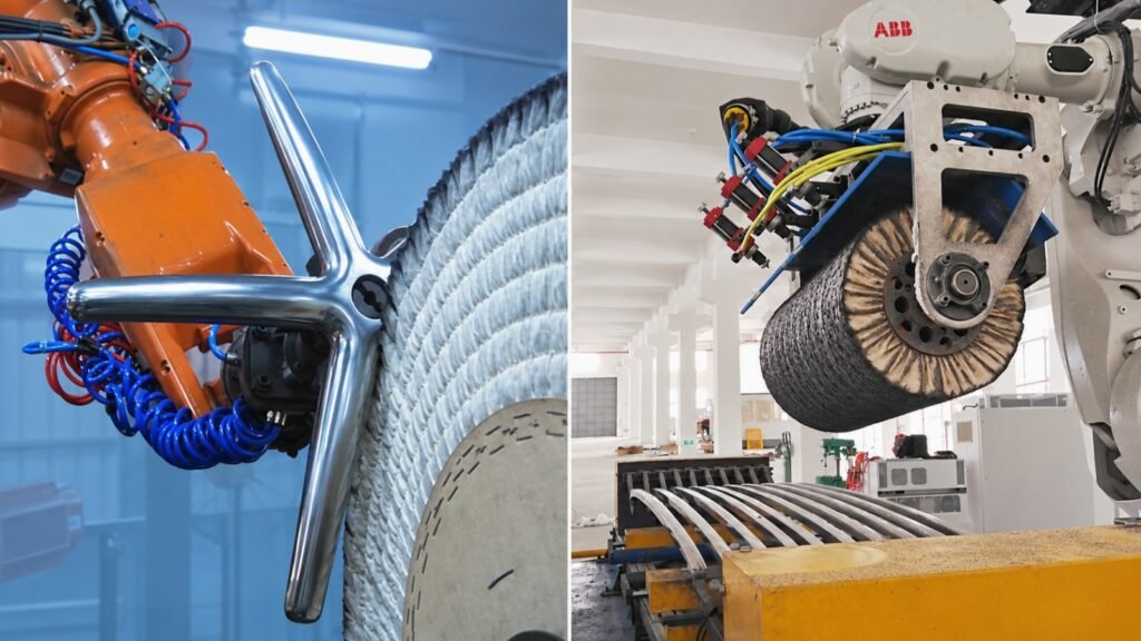
A robotic polishing cell does not always work in the same way. In one system, the robot grips the workpiece and presents it to stationary abrasive belts, sanding wheels or polishing wheels. In another, the workpiece remains fixed while the robot carries the finishing tool around it.
These two layouts are often described as robot-held workpiece and robot-held tool configurations. They can both be used for robotic grinding, sanding, polishing, buffing or deburring, but they place very different demands on the robot, fixture, tooling and production layout.
Neither configuration is automatically better. The correct choice depends on the part size and weight, center of gravity, required surfaces, process sequence, contact force, loading method, cycle-time target and available floor space.
This guide explains how the two configurations work, where each is normally useful and what manufacturers should confirm before choosing a robotic grinding and polishing system.
What Is a Robot-Held Workpiece Configuration?
In a robot-held workpiece configuration, a gripper mounted on the robot wrist holds the component. The robot then moves and rotates the part against one or more stationary finishing stations.
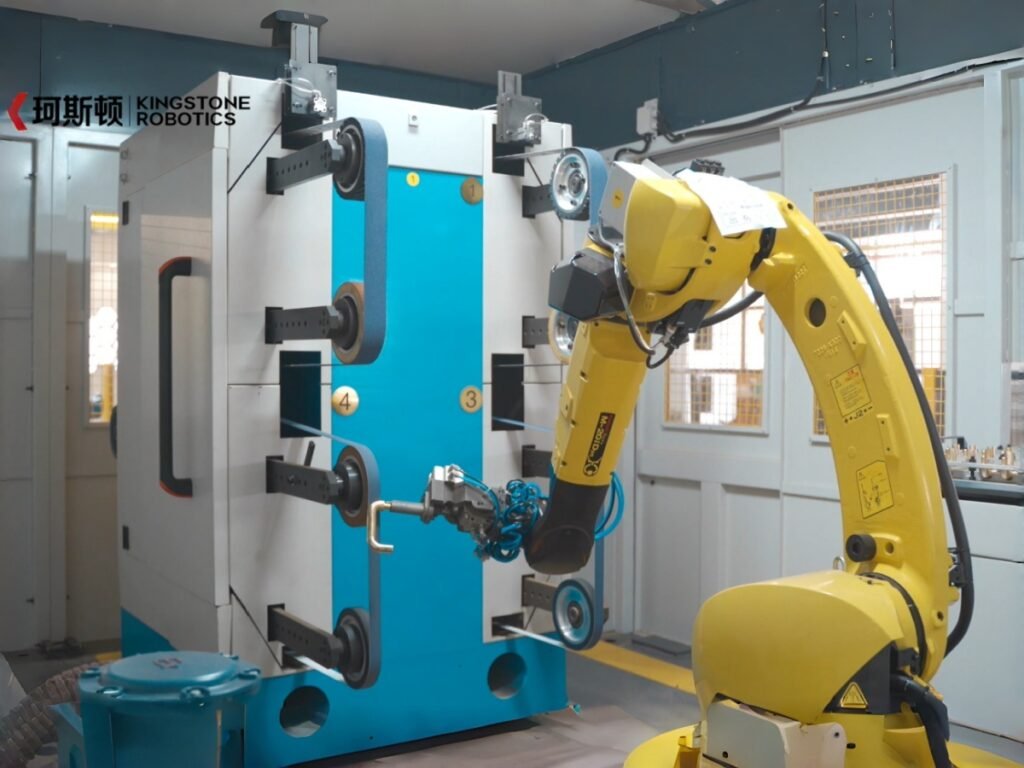
Depending on the required surface, the cell may include:
- Abrasive-belt grinding stations
- Flap wheels or non-woven abrasive wheels
- Sisal polishing wheels
- Cloth buffing wheels
- Compound application equipment
- Several rough-to-fine finishing stages
The robot controls how each area of the part approaches the abrasive, including its position, contact angle, path and movement speed. Contact pressure may be controlled through a compliant grinding or polishing unit, robot force control, or a combination selected for the application.
This configuration is commonly considered when the part is small or medium-sized, can be gripped securely and must be presented to several different finishing tools during one production cycle.
Main Advantages of a Robot-Held Workpiece
The workpiece can be reoriented continuously.
A six-axis robot can rotate the component so that curved surfaces, outside contours and several faces contact the finishing wheel at suitable angles.
Several stationary process stations can be used in one cell.
The robot can move the same part from rough grinding to fine sanding and then to polishing or buffing without carrying a different powered tool for every stage.
Heavy-duty finishing equipment remains stationary.
Large belt grinders and polishing motors do not consume robot wrist payload. Power cables, air lines and extraction ducts for those machines can also remain in fixed positions.
The configuration can suit repeated production of compact parts.
Faucet bodies, handles, lock components, small castings and similar parts are often practical candidates when they have reliable gripping areas and repeatable incoming dimensions.
Main Limitations of a Robot-Held Workpiece
The robot must carry more than the nominal weight of the component. The total wrist load includes the gripper, fingers, sensors, adapters and workpiece. The center of gravity, load offset and rotational inertia must also remain within the robot manufacturer’s limits throughout the motion.
Gripper design is equally important. It must resist grinding or polishing forces without allowing the part to move, yet it must not mark finished surfaces or block areas that need processing. If the part must be regripped during the cycle, the additional handling time and the risk of locating error must be included in the system design.
Very large, long, thin or awkward parts can also be difficult to carry safely. A part may be below the robot’s stated payload but still create excessive wrist torque or inertia because its center of gravity is far from the robot flange.
What Is a Robot-Held Tool Configuration?
In a robot-held tool configuration, the workpiece is secured in a fixture while the robot carries the finishing tool. The end-of-arm equipment may include a grinding spindle, belt tool, orbital sander, angle grinder, deburring tool or polishing head.
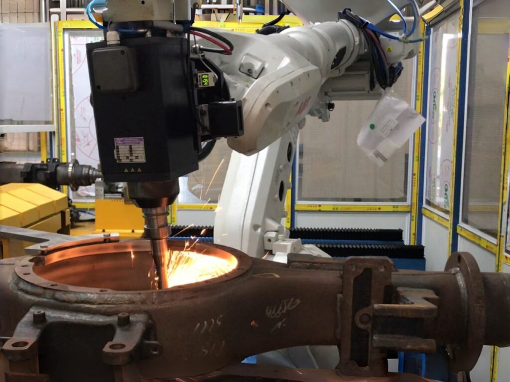
A compliant mechanism or force-control system may be installed between the robot and the tool to help maintain controlled contact. For multi-sided components, the fixed fixture may also be mounted on a rotary positioner so that additional surfaces can be exposed to the robot.
This layout is often considered when the workpiece is too large, heavy or inconvenient for the robot to carry, but a suitable finishing tool can be moved around the required areas.
Main Advantages of a Robot-Held Tool
Large or heavy workpieces can remain supported.
The robot does not need to carry the complete component. Castings, welded structures, long frames and other difficult-to-handle parts can remain in a rigid fixture during processing.
The workpiece can be located from stable production references.
A well-designed fixture can support the component close to the processing area and reduce movement caused by grinding force.
Local areas can be processed without moving the entire part.
If only selected welds, edges, seams or surface zones require finishing, the robot can bring the tool to those areas.
A positioner can expand access.
For some applications, a rotary or multi-axis positioner can turn the workpiece while the robot maintains a practical tool orientation.
Main Limitations of a Robot-Held Tool
The robot must carry the complete tool package. This may include the spindle or sander, motor, compliance device, force sensor, tool changer, dust shroud and mounting hardware. Their combined mass, center of gravity and inertia must be checked against the robot’s wrist capacity.
Power cables, pneumatic hoses, extraction hoses and other utilities also move with the robot. Their routing must allow the full programmed motion without excessive bending, snagging or collision.
Tool vibration and process reaction forces can affect surface quality if the robot, tool mount or workpiece fixture lacks sufficient stiffness. Tool access must also be checked carefully. A compact tool may enter areas that a large polishing wheel cannot reach, but its body, motor, guard or dust shroud can still collide with surrounding geometry.
When several abrasive stages are required, the cell may need automatic tool changing, multiple robot-carried tools or additional fixed process stations. These options add flexibility but also affect cycle time, maintenance and system complexity.
Robot-Held Part vs Robot-Held Tool: Practical Comparison
| Evaluation point | Robot-held workpiece | Robot-held tool |
|---|---|---|
| Typical workpiece situation | Small to medium parts that can be gripped and moved safely | Large, heavy, long or awkward parts that are better kept in a fixture |
| Robot carries | Gripper, adapters and workpiece | Finishing tool, compliance device and related hardware |
| Main workholding requirement | A secure gripper with accessible processing surfaces | A rigid, repeatable fixture that supports the workpiece during contact |
| Multiple finishing stages | Often practical to move the part between several stationary stations | May require tool changing, multiple tools or a hybrid cell |
| Utilities at the robot wrist | Usually fewer powered-tool cables and hoses | Power, air and extraction routing may move with the robot |
| Surface access | Robot reorients the part relative to fixed tools | Robot moves the tool around the fixed part; a positioner may assist |
| Large-part handling | Limited by payload, center of gravity, inertia and safe gripping | Often more practical because the part remains supported |
| Loading and unloading | Part must enter the robot gripper in a repeatable position | Part must be located repeatably in the processing fixture |
| Changeover work | May involve gripper fingers, trays and programs | May involve fixtures, tools, tool data and programs |
| Best choice | Determined by the complete process, not by one factor | Determined by the complete process, not by one factor |
The table provides general tendencies, not fixed rules. A small part may still be better processed in a fixture if it is delicate or difficult to grip. A relatively large part may still be robot-held if its weight, balance, gripping features and required motion make that approach practical.
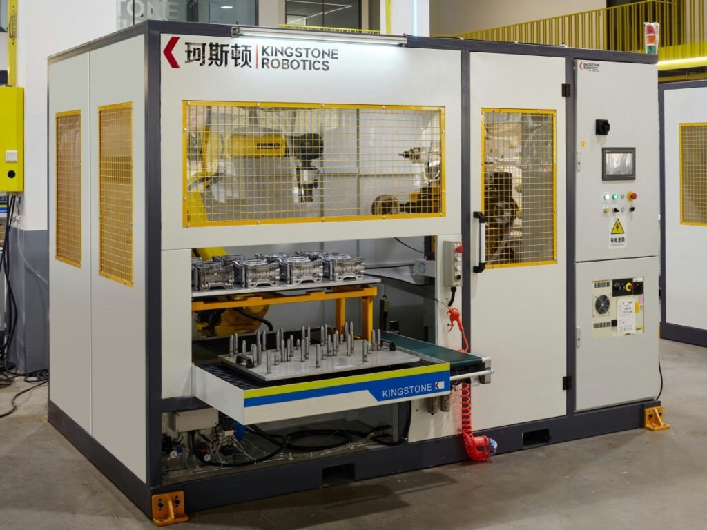
Eight Factors That Should Decide the Configuration
1. Required Finish and Complete Process Sequence
Start with the finished-part requirement, not the robot model.
A component that only needs one edge deburred presents a different automation problem from a decorative part that requires rough grinding, fine sanding, sisal polishing and cloth-wheel buffing. The number of tools, required contact conditions and order of operations can strongly influence which layout is practical.
Grinding, sanding, polishing and buffing should not be treated as interchangeable terms. Each stage removes or refines the surface differently. The selected configuration must support every required stage rather than only the most visually impressive final step.
2. Part Mass, Center of Gravity and Inertia
Part weight alone is not enough to select a robot-held workpiece layout.
The engineering check should include:
- Workpiece mass
- Gripper and adapter mass
- Distance from the robot flange to the combined center of gravity
- Load orientation during the complete path
- Rotational inertia of long or offset parts
- Dynamic forces created by acceleration and deceleration
- Contact forces during grinding or polishing
A robot’s brochure payload is only one limit. The selected robot and end-of-arm design must satisfy the manufacturer’s permitted wrist load, torque and inertia values for the actual motion.
3. Required Surface Access
Map every surface that must be processed, every surface that must be protected and every approach direction required by the abrasive.
For a robot-held part, check whether the gripper blocks an important surface and whether the workpiece can reach each stationary wheel without a robot or fixture collision.
For a robot-held tool, check whether the complete tool assembly—not only the abrasive contact point—can move around the part. Deep recesses, narrow gaps and internal surfaces may require a smaller or differently shaped tool.
If the feasibility of the component itself is still uncertain, review our guide to which metal parts are suitable for robotic polishing.
4. Part-to-Part Variation and Contact Control
The robot repeats its programmed motion, but incoming parts may not be identical. Castings can vary in flash height, parting-line position and local surface condition. Welded parts can vary in seam height or distortion.
In either configuration, these differences can change the actual contact between the abrasive and the workpiece. Depending on the application, stable processing may require appropriate compliance, force control, position or size detection, and compensation for abrasive wear.
Kingstone’s surface finishing technology combines process planning with options such as force control, inspection and consumable management according to the project. Not every application needs every function; the correct combination should be confirmed through testing.
5. Gripper or Fixture Design
A robot-held part needs a gripper that locates and secures the workpiece while leaving the processing areas accessible. A robot-held tool needs a fixture that supports the part against tool pressure and vibration.
In both cases, workholding should be designed early. Adding a gripper or fixture after the path and cell layout have already been decided can create blocked surfaces, unstable contact or impractical loading.
The design should also consider:
- Acceptable clamping areas
- Protection of cosmetic surfaces
- Datum and locating repeatability
- Resistance to process forces
- Manual or automatic loading
- Model changeover time
- Maintenance and cleaning access
6. Real Cycle Time
Do not compare the two layouts using contact time alone.
A complete cycle can include part loading, locating, gripping, transfers, processing at several stations, reorientation, tool changes, wheel conditioning, unloading and inspection. Some operations may overlap, while others must happen sequentially.
For example, a robot-held workpiece may move quickly between fixed abrasive stations but require additional gripping or orientation movements. A robot-held tool may avoid part handling but require a tool change or a positioner movement.
Our guide to robotic polishing cycle time explains how to calculate expected good parts from the complete repeated sequence rather than from robot speed alone.
7. Cell Layout, Dust Control and Maintenance
Grinding and polishing create dust, debris, heat and consumable wear. The configuration changes where these effects occur inside the cell.
With stationary belt or polishing stations, extraction can often be arranged around fixed dust-generation points. With a robot-held tool, the dust source moves with the robot and may require a suitable shroud, local extraction or cell-level collection strategy.
The layout should provide safe access for belt or wheel replacement, tool maintenance, gripper or fixture cleaning and finished-part inspection. Safety guarding, interlocks and dust-control equipment must be designed around the actual motion and process—not added after the main equipment has been placed.
For applications involving several tools or large workpieces, a customized robotic complex workstation may combine processing, positioning, tool management and safety functions in one cell.
8. Product Mix and Future Changeovers
Factories rarely produce only one component forever. The cell should therefore be evaluated against the expected product family, not only the first sample.
For a robot-held workpiece system, a new model may require different gripper fingers, locating trays and robot paths. For a robot-held tool system, it may require a different fixture, tool, contact parameters and path.
Products with similar materials, processing areas and finishing sequences are usually easier to combine. If the variants differ greatly in size, weight or required tools, one highly complex cell may be less practical than separate standardized processes.
Typical Application Examples
Faucets, Handles and Lock Components
Compact decorative parts often require several external surfaces to be ground and polished. When a reliable non-cosmetic gripping area is available, the robot-held workpiece layout can allow the component to move through several stationary abrasive and polishing stations.
This is only a general starting point. Thin walls, difficult gripping surfaces, deep internal areas or large casting variation can change the solution.
Large Castings and Welded Structures
When a component is too heavy or awkward to rotate safely with a robot, keeping it in a fixture and moving a grinding or deburring tool around it is often worth evaluating. The fixture may need to support areas close to the processing point, and a positioner may be required to expose additional faces.
Some castings can still be held by the robot and presented to a stationary belt grinder when their size, load and gripping features permit it. Our robotic grinding workstation examples show why the equipment must be configured around the actual part and process.
Long or Thin Decorative Components
Long trim, rails, tubes and thin formed parts require special attention to deflection and support. Carrying the complete component may create excessive inertia or allow it to vibrate. Fixing it too rigidly, however, may restrict access to surfaces on the opposite side.
Both architectures should be studied with the actual part. The final decision may depend on support spacing, acceptable gripping areas, surface access, robot reach and whether the component needs to be repositioned during the cycle.
When a Hybrid Configuration Makes Sense
Some projects cannot be reduced to a single architecture. A cell may use a fixed workpiece with a robot-held tool for one operation and a separate stationary finishing station for another. It may also use a positioner, automatic tool changer or more than one robot.
A hybrid layout can solve a genuine process problem, but it should not be added simply to make the cell appear more advanced. Every additional robot, axis, tool changer and transfer step increases programming, guarding, maintenance and cycle-time considerations.
The layout should remain only as complex as the production requirement justifies.
Why Representative Sample Testing Is Essential
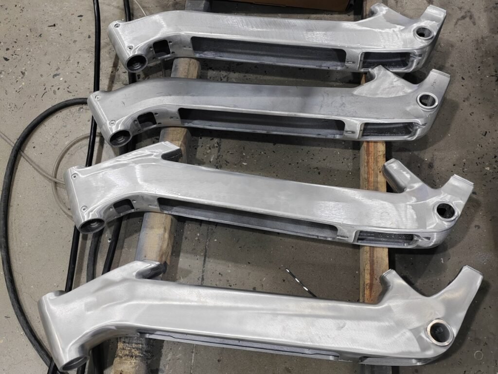
Photos and drawings are useful for an initial configuration study, but they cannot confirm the complete finishing process. Sample testing is needed to evaluate how the material responds to the selected abrasive, how much contact force is required, how the part varies and whether the target finish can be achieved consistently.
A meaningful trial should use representative raw parts rather than one specially selected easy sample. If possible, include parts from different batches and an accepted finished sample for comparison.
Testing should confirm:
- Required abrasive and grit sequence
- Practical contact angle and path
- Contact force or compliance strategy
- Number of passes
- Gripper or fixture stability
- Accessibility of every required surface
- Effect of normal part variation
- Consumable wear and compensation
- Repeatable cycle time
- Finished-part acceptance criteria
The configuration should be selected after these factors are understood, not before.
Information to Send for a Configuration Review
For an initial robotic polishing assessment, prepare:
- Clear photos of the complete raw part
- A drawing or 3D model with dimensions
- Part material and manufacturing method
- Part weight and, if known, center-of-gravity information
- Marked images showing surfaces to process and areas to protect
- Current grinding, sanding, polishing or buffing sequence
- Current abrasives, polishing wheels and compounds
- An accepted finished sample or clear quality standard
- Required good parts per hour or per shift
- Product variants and expected changeover frequency
- Available floor space and preferred loading method
- Several representative raw samples for process testing
A short video of the current manual process is also valuable. It shows how the operator holds or supports the part, which areas require the most work and where process judgment is currently being used.
Frequently Asked Questions
Is a robot-held workpiece more accurate than a robot-held tool?
Not automatically. Finished quality depends on part locating, gripper or fixture stiffness, robot and tool selection, contact control, abrasive condition, path development and incoming-part variation. Either layout can produce stable results when the complete process is engineered correctly.
Which configuration has a faster cycle time?
There is no universal answer. A robot-held workpiece may move efficiently between several fixed stations, while a robot-held tool may avoid moving a heavy component. Loading, transfers, reorientation, tool changes, consumable maintenance and inspection must all be included in the comparison.
Does part weight alone determine the layout?
No. Weight is important, but center of gravity, inertia, gripper mass, workpiece length, robot reach, surface access and process forces can be equally important. A light but very long part may be harder to carry than a compact heavier part.
Can one cell use both stationary and robot-held tools?
Yes. A hybrid cell can combine different processing methods when the part genuinely requires them. The added cost, programming, maintenance, safety and cycle-time impact should be justified by the production need.
Is force control useful in both configurations?
It can be. Both layouts involve contact between an abrasive and a workpiece. The required compliance or force-control method depends on the part geometry, process, material variation and finish standard. It should be validated with actual samples.
Can the layout be chosen from part photos alone?
Photos can support an initial recommendation, but a final configuration normally requires dimensions, weight, process details, production targets and representative sample testing. A manual-process video and accepted finished sample make the assessment more reliable.
Choose the Configuration From the Part and Process
The most important question is not whether the robot should hold the part or the tool in general. It is which arrangement gives this specific component reliable access, stable contact, safe handling, practical loading and a repeatable cycle.
Robot-held workpiece systems are often effective for compact parts that can be gripped securely and moved between several stationary finishing stations. Robot-held tool systems are often practical for large or heavy components that should remain supported. Hybrid layouts can solve more complex requirements when their additional complexity is justified.
The final choice should be based on the complete process and confirmed with representative parts.
If you are planning a polishing, grinding or deburring project, contact our engineering team with your part drawings, photos, material, dimensions, weight, current process, target finish and required output. We can review the workpiece and recommend a suitable configuration for sample testing and production.