
A part may look bright under workshop lighting and still show scratches at the customer’s inspection station. A smooth outer face may pass a roughness check while a nearby edge has been rounded beyond its drawing requirement.
For manufacturers evaluating robotic polishing, these situations raise a practical question: what exactly makes a finished part acceptable?
Robotic polishing surface finish requirements should connect the intended appearance with measurable texture, protected features and a repeatable inspection method. Defining these requirements early gives the customer and equipment supplier a common target for process development and production approval.
Define Quality at the Correct Production Stage
Start by identifying where the polished part goes next. A component sent directly to assembly may need a final decorative finish. A component sent for plating needs an agreed surface condition before that downstream process.
Record the material, incoming surface, areas to be processed and required output condition. Identify whether the inspection takes place after grinding, after final buffing, after cleaning or after a later surface treatment.
For plated products, agree both the polished substrate requirement and how representative parts will be assessed after the intended plating process. Record the downstream processing conditions so that a change in plating is not confused with a change in polishing.
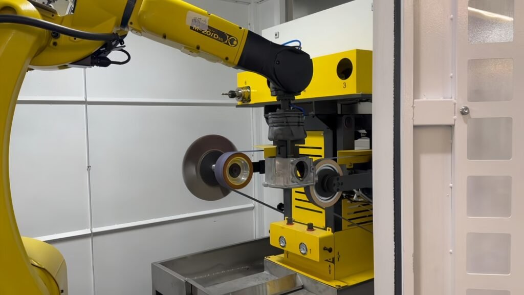
This information helps define the sequence and tooling for a robotic grinding and polishing system.
Review Four Aspects of Surface Quality
1. Visual appearance
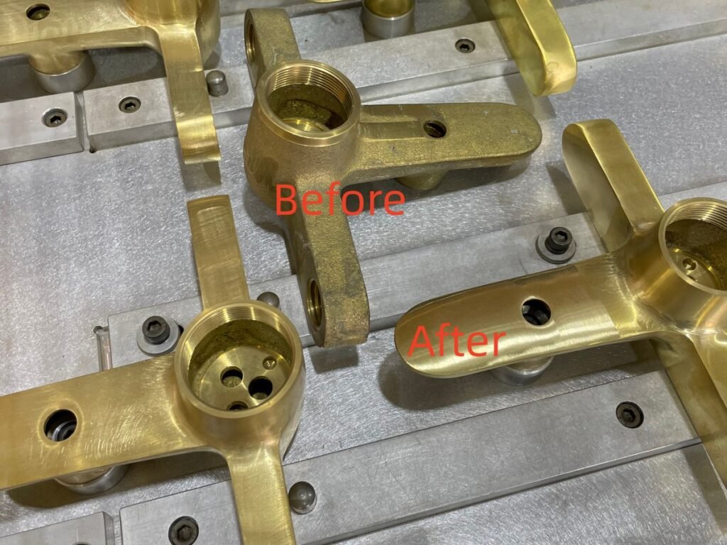
Describe the required appearance using an approved physical sample and written criteria. Terms such as “bright,” “smooth” and “mirror finish” need supporting references.
Specify the permitted condition of visible faces, transitions and recessed areas. Depending on the application, the review may cover residual scratches, patchy reflection, inconsistent grain direction, local dull areas and clamp marks.
Gloss measurement evaluates specular reflection under a defined instrument geometry. Use an agreed method where gloss is specified, and assess visible defects separately.
For decorative components that need a bright final appearance, a robotic buffing cell can be evaluated as part of the finishing sequence. Confirm the result on the actual part.
2. Surface roughness
Ra expresses the arithmetic average of the absolute profile deviations from the mean line over the specified length. It provides information about texture along the measured profile.
Treat the specified roughness value as one part of the acceptance plan. Inspect the other required characteristics, including appearance and geometry, using their own agreed checks.
When a drawing specifies roughness, record the parameter, unit, limit, measurement location, trace direction and instrument settings. Identify the applicable drawing specification and measurement method, including filtering and evaluation length.
Agree how curved or restricted areas will be measured. Keep the measurement setup consistent when comparing trial parts with later production parts.
3. Burr and edge condition
State which burrs or parting lines must be removed and which edges must retain a defined shape. “Burr-free” should be connected to identified locations and an agreed inspection method.
Check transitions around holes, openings, corners and parting lines. Where an edge radius or chamfer is specified, evaluate it against the drawing. Record any permitted edge break rather than leaving the operator to interpret it.
4. Dimensions and protected features
Mark features that need dimensional inspection after finishing. These may include thin sections, sealing faces, mounting surfaces, small radii and assembly interfaces.
Also identify surfaces where abrasive contact is prohibited. The process plan should show how those areas remain protected while adjacent surfaces are finished.
Where a part is marked or processed unevenly near its holding points, review the workholding arrangement. Our robotic polishing fixture design guide explains how locating, support and tool access affect finishing.
Map Finish Requirements to Individual Areas
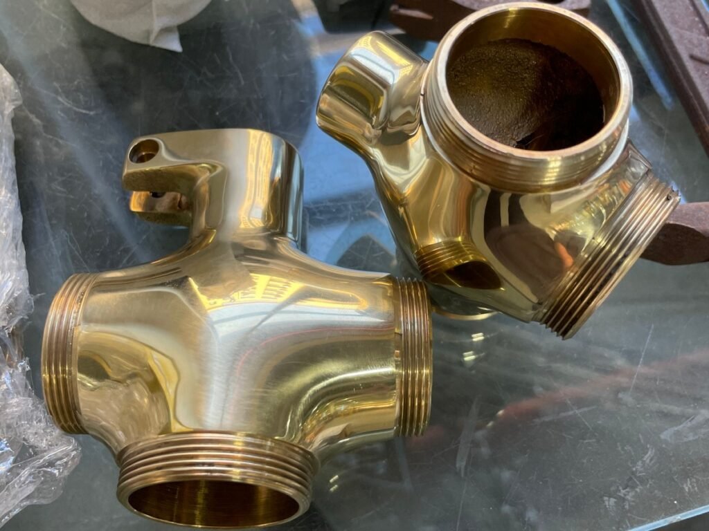
A part rarely needs exactly the same treatment everywhere. Mark the finishing zones on a drawing or annotated photograph and connect each zone with its inspection requirements.
The following table is an example of how to organize the discussion. Actual limits and methods must come from the part specification and agreed trials.
| Part area | Requirement to define | Verification to agree |
|---|---|---|
| Main visible face | Appearance, scratch limits and roughness where specified | Reference sample comparison and measurements at marked locations |
| Curved transition | Finish coverage, blend appearance and permitted shape change | Inspection from agreed views and profile checks where required |
| Opening or edge | Burr condition, edge break, radius or chamfer | Specified edge inspection or dimensional measurement |
| Functional or protected face | Permitted material removal and surfaces to avoid | Drawing-based checks and confirmation of the protected area |
This zone map gives process engineers a basis for selecting tool approaches and gives inspectors a clear record of where each requirement applies.
Standardize How Parts Are Inspected
Create an inspection setup that the customer and supplier can reproduce.
Agree the lighting, viewing distance, viewing angles, background and part orientation for visual assessment. Identify how the part will be cleaned before inspection and which physical reference sample will be used.
For instrument checks, record the equipment, measurement locations, setup and calibration status. Confirm that the selected instrument can assess the actual geometry.
Photographs are useful for documenting inspection areas and defect examples. Use consistent lighting and camera settings when comparing images, and retain the agreed physical references for approval.
Include acceptable and unacceptable examples where practical. Give reference samples an identification number and revision so that both teams know which finish has been approved.
Check Consistency Across a Production Run
A successful demonstration part is a starting point for validation. Production approval should also examine whether the agreed result is repeated during normal operation.
Choose trial parts that represent the expected incoming condition. Where relevant, include typical variation between batches and around the areas that are most difficult to finish.
Agree a trial that checks consecutive parts and relevant operating conditions. These can include:
- Parts produced after the abrasive has been prepared for use.
- Parts produced later in the agreed abrasive service interval.
- Parts produced after a normal production stop and restart.
- The first accepted parts after a model or tooling change.
Use the same inspection criteria throughout the trial. Record adjustments, rework, rejected parts and any additional manual finishing.
Evaluate output using the number of accepted parts produced in the measured period. Our robotic polishing cycle time guide explains how handling, finishing stages and production losses affect capacity planning.
Record What Was Approved
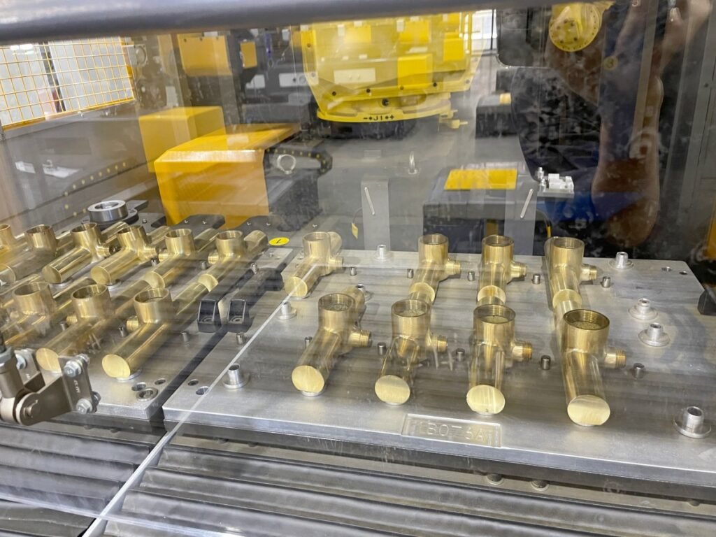
Keep the finished sample, inspection record and process setup connected.
An acceptance record should identify the part number and drawing revision, incoming condition, marked finishing zones, finish criteria, inspection method, trial results and approved reference samples.
Record the associated tooling and program revisions, abrasive sequence and validated process settings. State whether any manual touch-up forms part of the approved production process.
If the material, casting source, geometry or required finish changes, review whether the existing approval still applies. Define the checks needed before releasing the changed process for production.
Frequently Asked Questions
Is Ra enough to approve a polished surface?
Ra is useful when roughness is specified. Appearance, local defects, edge condition and dimensions need their own acceptance checks. Select the combination required by the component’s purpose.
What Ra value should a robotic polishing system achieve?
The target should come from the part’s functional requirement, drawing or an agreed finish specification. Feasibility must be evaluated using the actual material, geometry, incoming surface and proposed process.
How should a mirror finish be specified?
Provide an approved physical sample and define the inspection conditions, permitted defects and required finishing zones. Add quantitative measurements where they are relevant and practical for the part.
Should quality be checked before or after plating?
For a plated component, agree the required condition after polishing and evaluate representative parts after the intended plating process. Keep the acceptance stage and responsibility for each process clear.
How many samples are needed for approval?
Agree the sample quantity and trial duration according to the part variation, process risks and customer requirements. The trial should provide evidence of repeatability under the operating conditions being approved.
Define Your Surface Finish Requirements With Kingstone Robotics
Send Kingstone Robotics your part drawings or photos, material, dimensions, incoming surface condition and required production output. Mark the surfaces to finish, protected features and critical dimensions.
Include an approved finished sample or a written finish specification where available. This gives our team a basis for reviewing the tooling, processing sequence and validation work needed for your application.
Contact our team to discuss your robotic polishing project.
Email: info@automatedpolish.com
WhatsApp: +86 151 5987 5082