Manufacturers of faucets, handles and other metal components often produce several models in the same workshop. Each model may have a different length, gripping feature, surface profile or finish requirement. For these manufacturers, the production plan needs to include both finishing cycles and the work required to switch products.
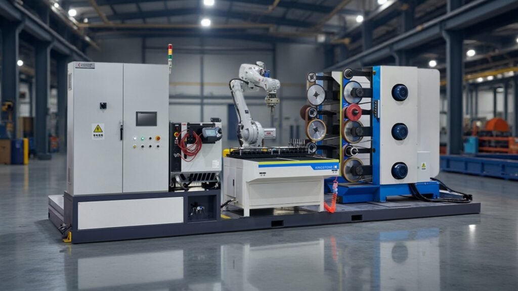
Robotic polishing changeover is the transition from an approved setup for one part model to an approved setup for another. It can involve fixtures, robot programs, abrasives, loading arrangements and inspection references. Planning these elements together helps determine whether a robotic grinding and polishing cell is practical for the proposed product mix.
Identify Which Part Models Can Share a Cell
Start by grouping parts according to their processing requirements. Similar appearance alone does not establish compatibility. Two handles may look alike while requiring different gripping methods or access to different surfaces.
Review the models against the robot’s reach and load requirements, holding features, finishing areas, abrasive sequence, incoming condition and accepted finish. Include the gripper or tool assembly in the load assessment, together with the workpiece position and motion.
The overall layout also matters. A robot-held workpiece cell and a robot-held tool cell can involve different changeover tasks. Our guide to robot-held parts versus robot-held tools explains how the handling configuration affects this decision.
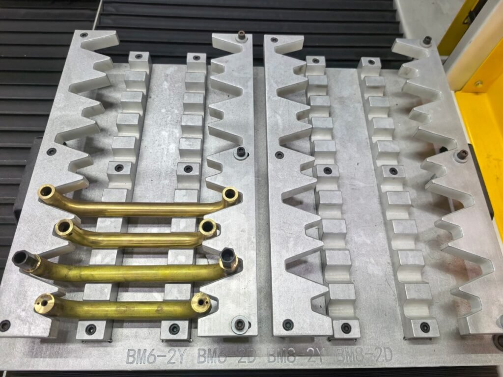
Build a Model-by-Model Setup Matrix
Create a setup record for every proposed model before finalizing the cell specification. This makes shared equipment and model-specific requirements easier to compare.
| Setup element | Record for each part model |
|---|---|
| Workpiece | Part number, drawing revision, material and incoming condition |
| Holding equipment | Gripper fingers, fixture nest, supports and locating references |
| Finishing tools | Required stations, abrasive types, grit stages and polishing media |
| Program and settings | Approved program revision, tool data and process settings |
| Loading | Tray or pallet arrangement, orientation and pickup or seating position |
| Inspection | Accepted reference, processing zones and required measurements |
Use consistent identifiers across the setup record, tooling and program selection. The operator should be able to match the part model with its approved equipment and settings without relying on memory.
Review What Needs to Change Between Models
Gripper fingers, fixtures and supports
Parts with compatible locating and gripping features may share some tooling. Other models may need replaceable fingers, different fixture inserts or a separate gripper. Check that each arrangement holds the part securely and leaves the required surfaces accessible.
Cleaning and locating are part of the switch. Debris on a contact face can affect how the next part seats. Define which faces need inspection and how replaceable elements return to their approved position. The robotic polishing fixture design guide covers the workholding factors behind repeatable finishing.
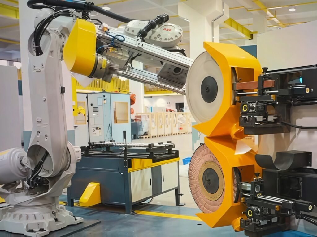
Robot programs and associated data
A stored program makes a previously validated model easier to run again. Its setup still needs to match the installed tooling, part location and finishing stations.
Identify the program revision and the associated tool, workpiece and process data for each model. Changes to a gripper, tool position or locating feature should be reviewed for their effect on the existing path. Introducing a new model also requires process development and validation, which should be scheduled separately from routine switching between approved models.
Abrasives, polishing media and process settings
Compare the complete finishing sequence across the product family. One model may require casting-mark removal followed by fine sanding, while another arrives with a surface ready for buffing. Different materials or appearance targets can also require different media and contact settings.
Record which tools remain installed, which consumables change and whether a wheel needs conditioning before production resumes. Where surface contamination matters, agree how tools and media will be separated or cleaned between materials and compounds. Validate the proposed arrangement with the relevant parts.
Loading and unloading arrangements
The robot’s processing setup and the part-presentation setup need to change together. A different model may require another tray, pallet insert, pickup position or unloading location.
Review how the incoming part is oriented and how the correct setup is confirmed. Clear identification, suitable locating features or engineered detection can support the process. Specify the method needed for the application rather than assuming automatic model recognition is included.
Inspection references
Keep the acceptance criteria connected to the model being produced. A mirror-finished handle, a satin-finished fitting and a component prepared for plating may have different visual and measurement requirements.
The setup record should identify the correct reference sample, protected edges, dimensional checks and any specified roughness measurements. This allows the first part after a switch to be assessed against the intended finish.
Measure Changeover From the Last Good Part to the First Good Part
For production planning, define changeover time as the elapsed time between the last accepted part of model A and the first accepted part of model B, using an agreed measurement method. Record what happens during that interval.
The interval may include clearing the previous batch, cleaning, replacing tooling, selecting the program, preparing consumables, confirming the setup and inspecting the first finished part. Time spent searching for a fixture or waiting for approval also affects when accepted production resumes.
An illustrative calculation shows why frequency matters: three changes lasting 12 minutes each use 36 minutes of a shift. These values are planning examples, not performance figures for a Kingstone system. The actual duration must be measured with the proposed models and operating procedure.
Record first-part processing and inspection explicitly so their time is counted once in the capacity calculation. If changeover losses are already included in another measured production allowance, avoid deducting them again. See the robotic polishing cycle time guide for the other activities that affect good parts per shift.
Confirm the First Run After a Model Change
A repeatable changeover procedure should link the new part number with the installed tooling, approved program and selected process settings. Follow the cell’s approved setup and restart procedure when making physical changes or checking motion.
Inspect the first finished part for coverage, local defects, clamp marks, edge condition and specified dimensions. Confirm that the correct finishing stages have been completed. Record any adjustment before continuing production.
During commissioning, test the proposed switches as well as steady production. An A-to-B change followed by a B-to-A change can reveal whether tooling, settings and references return consistently to their approved condition. Include representative operators and normal production parts in this assessment.
Match Changeover Equipment to the Production Schedule
The amount of changeover automation should follow the product mix and switching frequency. Replaceable fixture inserts or a manual tooling exchange may be practical for scheduled batches. Frequent switches may justify additional equipment for exchanging grippers or tools automatically.
A tool changer handles one part of the transition. Loading arrangements, abrasive preparation, program selection and quality approval still need to fit the overall sequence. Assess the complete changeover when comparing equipment options.
Batch scheduling can also reduce repeated setup work. Where delivery requirements allow, group models with compatible fixtures, media and finish requirements. Review the benefit alongside inventory, order deadlines and each model’s demand.
Frequently Asked Questions
Can one robotic polishing cell process different part models?
Yes, when the models fit the cell’s handling and finishing capabilities. Evaluate each model’s tooling, access, process sequence and quality requirements, then validate the intended setups and transitions.
Can several models use the same robot program?
Compatible variants may share part of a program or use a validated parameter-based approach. Different geometry or finishing zones can require separate paths. Confirm the approach with actual parts and keep the approved settings identifiable.
Is an automatic tool changer necessary for multi-model production?
It depends on the tooling differences and switching frequency. Compare the total changeover duration, operating effort and equipment cost for the proposed schedule. Some applications can use manual exchanges or replaceable inserts effectively.
Does changing the program complete the changeover?
Program selection is one step. The fixture, tool data, abrasives, loading arrangement and inspection reference must also correspond to the selected model.
How should changeover time be confirmed before acceptance?
Agree the timing boundaries and perform representative switches on the completed cell. Measure the interval through first-part approval, record adjustments and check whether the procedure works consistently for the proposed product mix.
Plan Your Multi-Model Polishing Application With Kingstone Robotics
Send Kingstone Robotics the drawings or photos of your proposed part family, materials, dimensions, weights, required finishes and production quantities. Include expected batch sizes and how often models need to change.
Our team can review the processing and handling requirements and discuss suitable tooling, cell configuration and validation steps for your product mix.
Contact our engineering team to discuss your robotic grinding and polishing project.