Two castings with the same part number can need different amounts of finishing. One may have a taller parting line, another may sit slightly differently in the fixture, and a third may arrive with deeper surface marks.
Robotic polishing for castings must account for these differences. The practical starting point is to identify what varies, decide which incoming conditions the cell should accept, and test how the workholding and finishing process respond. This applies to aluminum and zinc die castings, brass components, and iron or steel castings, with tooling and process settings selected for each application.
Why Robot Repeatability Does Not Guarantee the Same Finish
A programmed robot path describes motion relative to defined references. If the casting surface moves relative to those references, the actual contact with the abrasive changes.
A raised area may meet the tool earlier or more aggressively. A lower area may receive insufficient contact. A part that shifts during loading can move the finishing path away from the intended surface.
These problems can look similar on the finished component, but they need different corrections. Improving the loading fixture addresses a positioning problem. Changing the abrasive sequence addresses a material-removal problem. The first task is to tell them apart.
Separate Four Types of Casting Variation
Use incoming samples and marked photographs to classify the differences that affect finishing.
| Type of variation | What to examine | What the process review should establish |
|---|---|---|
| Loading and locating | Seating surfaces, orientation and clamp engagement | Whether each part reaches a repeatable position before processing |
| Local geometry | Surface height, contour and parting-line position | The range the tool path and contact arrangement must accommodate |
| Removal requirement | Flash thickness, raised marks and existing scratches | Which areas need grinding, finer finishing or additional preparation |
| Casting defects | Pits, cracks, distortion or other suspect areas | Which conditions require upstream review, separate rework or rejection |
Keep surface defects separate from removable excess metal. Grinding removes material; it does not fill a pit. Attempting to blend out a deep defect may remove more surrounding material than the drawing permits.
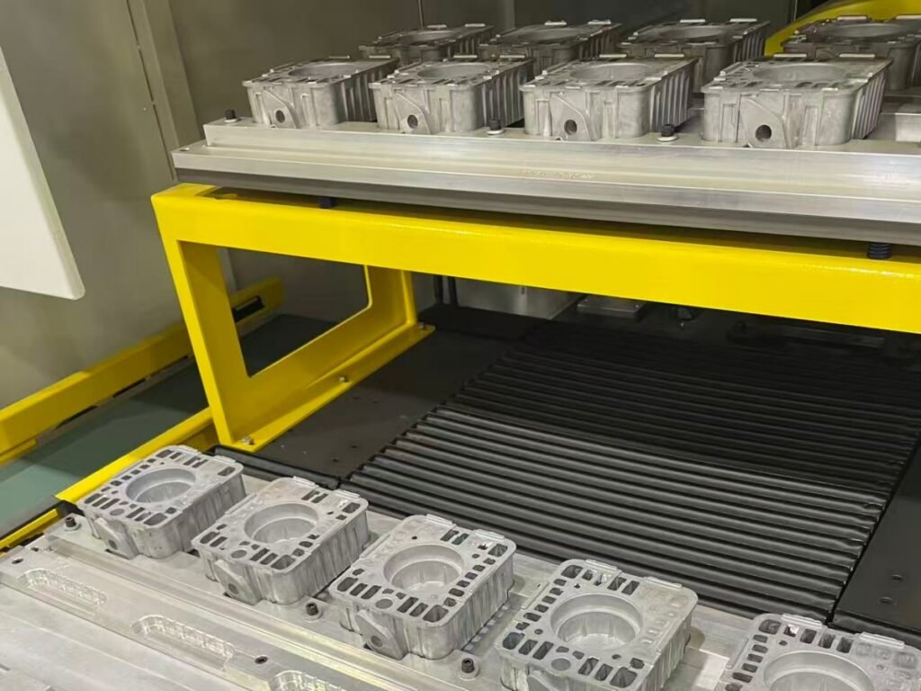
Define Which Incoming Parts the Cell Will Accept
Specify the production stage at which parts enter the cell. An as-cast component and a component that has already been trimmed and machined may need different handling and finishing steps.
For each part model, agree:
- The locating features and permitted dimensional range.
- The locations and acceptable size range of flash or raised material.
- The starting surface condition after upstream operations.
- The surfaces to finish and the features to protect.
- The conditions that require separate inspection or rework.
Use actual measurements where limits are important. A single tolerance value cannot describe every relevant difference across a complex casting.
The incoming-part specification should connect with the required finished condition. Our guide to robotic polishing surface finish acceptance criteria explains how to define appearance, edges, dimensions and inspection methods.
Match Each Problem to the Appropriate Control
Establish a Reliable Locating Method
Choose references that allow consistent seating without relying on loose flash or an irregular surface. Check that clamps hold the part securely and that finishing loads do not cause movement or unacceptable deflection.
Where practical, reload the same casting several times during setup checks. If its position changes, investigate loading and workholding before changing the polishing path. Then compare different castings to identify the additional effect of part geometry.
Our robotic polishing fixture design guide covers locating, support and access considerations in more detail.
Select Suitable Compliance or Force Control
Depending on the application, mechanical compliance or sensor-based force control can help the tool maintain suitable contact as the surface position changes. Sensor feedback can also support adjustments to motion or speed when the installed system provides those functions.
The required response must be tested on the component. Contact force alone does not determine how much material is removed; abrasive condition, contact area, speed and dwell time also matter.
Check the system’s working range and its response when contact conditions exceed the agreed limits. Force control cannot make every incoming casting acceptable.
Separate Heavy Removal from Surface Refinement
A thick parting line and a light polishing mark represent different finishing tasks. Where necessary, use a defined removal stage before finer sanding or polishing.
Avoid increasing pressure across the entire component to compensate for one difficult area. Develop local paths and process settings around the areas that actually need additional work. Our robotic grinding and polishing systems can be evaluated around the required sequence.
Add Position Checks When They Solve a Defined Problem
Part-presence checks, seating checks or vision-based position measurement may be useful where loading variation cannot be adequately controlled by the mechanical arrangement alone.
Specify what must be detected and what the cell should do with the result. Detecting part position does not by itself measure flash thickness or confirm finished surface quality. Each inspection function needs its own validation.
Test the Expected Range of Production Parts
Build the trial around normal production variation. Where relevant, identify samples by casting batch, mold cavity or supplier so that differences can be traced.
Include typical parts and parts near the agreed incoming limits. Keep known nonconforming samples clearly identified if they are used to evaluate detection or handling decisions.
During testing, record the sample identity, incoming condition, fixture setup, abrasive sequence, process settings, processing time and inspection result. Note any manual adjustment or touch-up needed to achieve acceptance.
Also check the process under relevant consumable conditions, including after normal abrasive replacement and later in the agreed service interval. This helps separate casting variation from changes caused by the finishing tool.
Agree sample quantity and trial duration around the application. A successful demonstration establishes an initial result; the production decision needs evidence that the specified range of parts can be processed consistently.
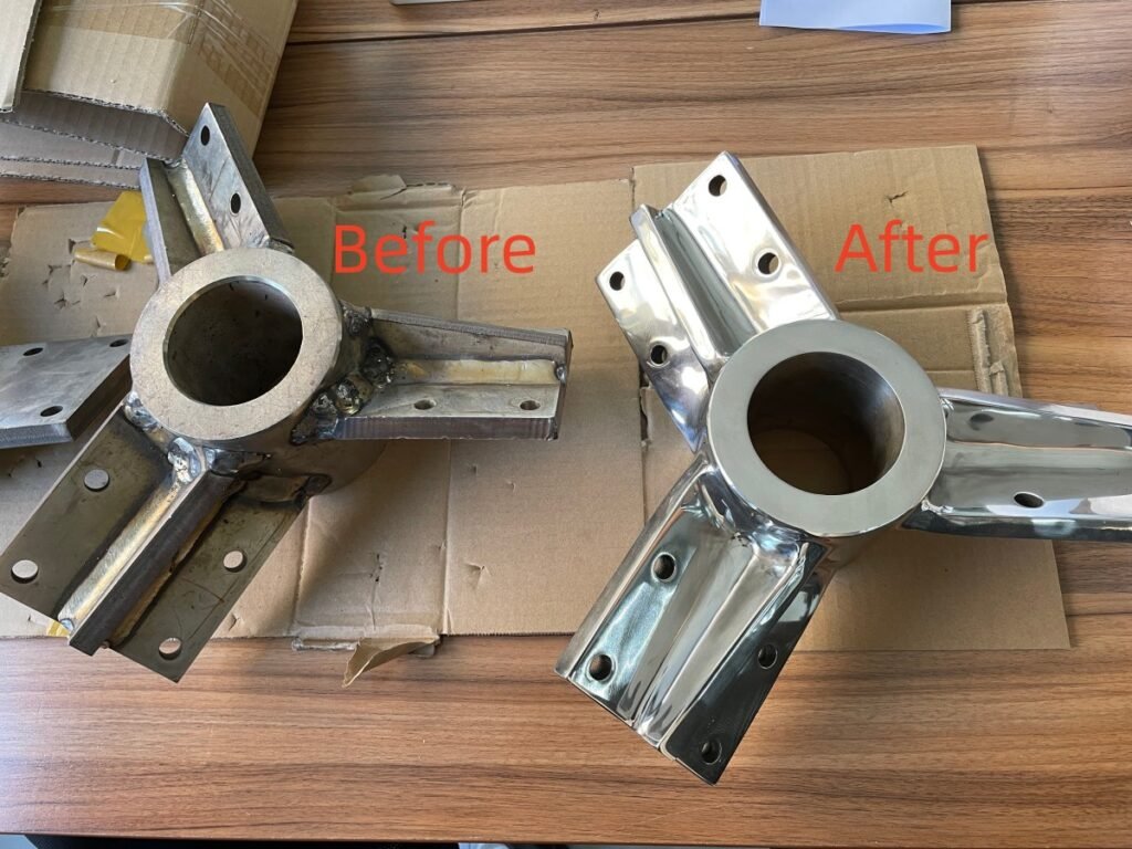
Example: Reviewing a Zinc Alloy Faucet Body
Kingstone’s zinc alloy faucet grinding and polishing application uses internal gripping to leave the outer surface available for finishing.
For a new faucet model, the review should check both the gripping opening and the exterior casting. Does the internal feature locate the part consistently? Does flash vary around a visible transition? Which faces must retain their shape before plating?
Those questions connect the holding method with the actual removal requirement. Sample trials can then establish the appropriate finishing stages. Where plating follows polishing, agree the substrate requirement and assess representative parts after the intended downstream process.
Frequently Asked Questions
Can the Same Robot Program Process Every Casting of One Model?
A validated program can serve parts within its approved incoming range. Changes in geometry, material, locating features or finishing requirements should trigger a review. The part number alone does not prove that the existing setup remains suitable.
How Much Casting Variation Can a Robotic Cell Handle?
There is no universal value. The answer depends on where the variation occurs, tool access, fixture design, available compliance or sensing, and permitted material removal. Confirm the range through measurements and trials on representative parts.
What Should We Check When Finish Quality Changes Between Batches?
First check seating and clamping, then compare the incoming geometry and surface condition. Also review abrasive condition, tool setup and any recent process changes. Change one controlled factor at a time so that the cause can be identified.
Discuss Your Casting Finishing Project
Kingstone Robotics develops grinding and polishing solutions around the workpiece and required result. For an initial review, share:
- Part photos or drawings, material, dimensions and weight.
- Close-ups showing typical casting variation and areas to finish.
- The current process and required finished condition.
- Target output and the number of part models.
- Representative raw samples and an approved finished reference, where available.
Discuss your application with our team so we can review workholding, finishing stages and the sample-testing requirements for your project.