A robot can repeat the same motion on every cycle. The workpiece, however, may not return to the same position. A casting can sit differently against a locator, a thin section can flex under a clamp, or polishing debris can collect on a support. Each change affects where and how the abrasive contacts the part.
That is why robotic polishing fixture design should begin while the finishing process is being planned. Workholding determines which surfaces the robot can reach, whether contact remains stable, how quickly parts can be loaded and whether a finished surface is marked by the clamp.
This guide covers seven practical checks for a robot gripper or stationary fixture. It also explains how to test the proposed design with representative production parts before the cell layout is finalized.
What Does the Fixture Need to Do?
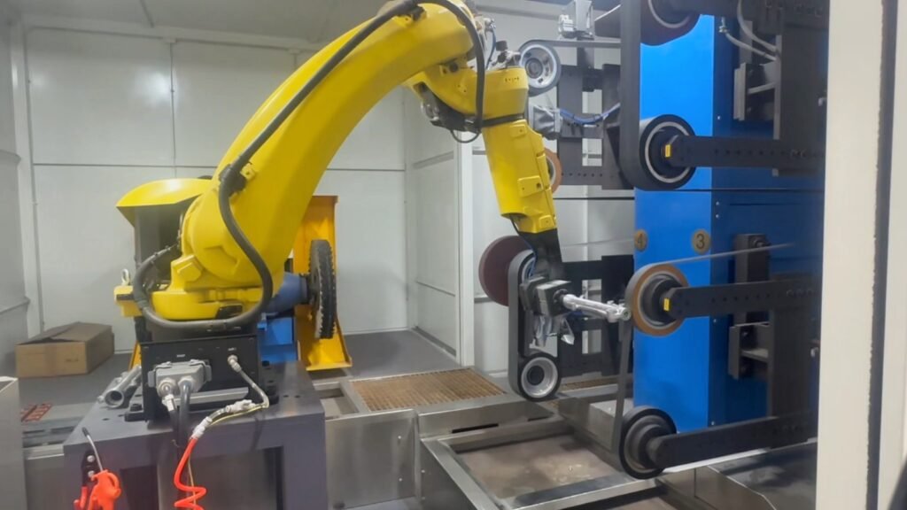
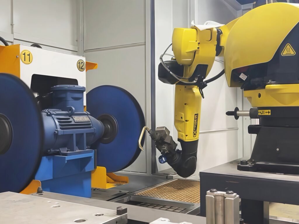
In a robot-held workpiece cell, an end-of-arm gripper locates the component and carries it to stationary abrasive belts or polishing wheels. In a robot-held tool cell, the part stays in a fixture while the robot moves the finishing tool around it. Both arrangements need a reliable relationship between the workpiece and the programmed path. Our guide to robot-held parts versus robot-held tools explains how to select the overall configuration.
The workholding task is more specific: put each raw part in a predictable position, keep it secure during contact and leave the required surfaces available for processing. The best design also allows safe loading, inspection, cleaning and changeover in normal production.
Seven Checks for a Robotic Polishing Fixture or Gripper
1. Choose locating features that exist on real production parts
Start by identifying the surfaces or features that establish the part’s position. A machined bore, a stable internal feature or a controlled mounting face may provide a more reliable reference than a rough cast exterior. The choice depends on the actual drawing and manufacturing process; no single datum strategy suits every part.
Check where incoming parts vary. If a casting seam or excess flash lies against a locator, the component may sit at a different angle from one cycle to the next. If the reference itself changes between batches, a repeatable robot path cannot correct the locating error on its own. Compare parts from normal production, including the variation the finishing cell is expected to accept.
2. Keep clamps away from required and visible finish areas
Mark three types of areas on a part drawing: surfaces to finish, surfaces that may be gripped and surfaces that must not be marked. This makes conflicts visible before designing the gripper fingers or clamp pads.
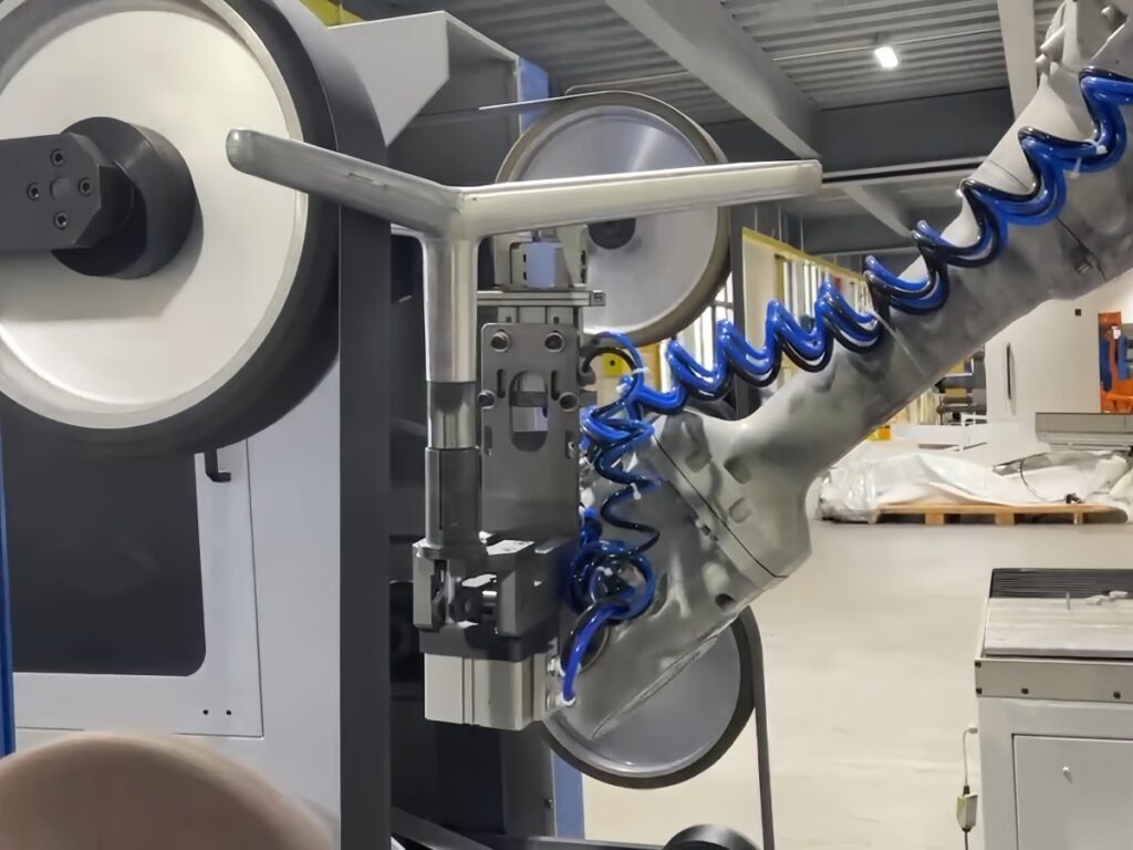
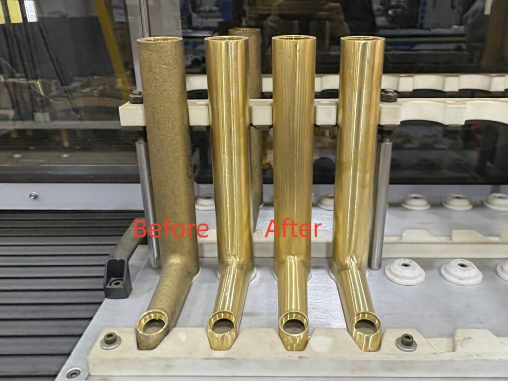
For example, Kingstone’s zinc alloy faucet grinding and polishing solution grips the faucet through an internal opening, leaving its curved exterior available for finishing. That is an application-specific approach. Another part may need a different internal grip, an external clamp on a non-cosmetic area or a second holding step.
Even a protective pad should be checked on actual samples. It must hold the part during processing without leaving an unacceptable impression or collecting abrasive particles against a visible surface.
3. Support the part against finishing forces without distorting it
The fixture has to resist the direction of the grinding or polishing force. A part that is firmly clamped at one end can still deflect at an unsupported area where the tool makes contact. The result may be uneven material removal, chatter or a changing contact angle.
Long rails, thin castings and formed metal parts deserve particular attention. Supports may need to be placed near the processing area, while the clamp load and contact shape must avoid bending the component before finishing begins. More clamping force is not automatically the solution: the fixture, the part and the finishing tool need to be evaluated together.
When the robot holds the part, include the gripper and adapters in the robot load assessment, along with the workpiece’s position and motion. If the part stays fixed, check the stiffness of the fixture and any rotary positioner throughout the tool path.
4. Check access with the complete abrasive tool, not just the contact point
Overlay the gripper, fixture, abrasive belt or wheel, guards and robot motion on the part’s required finishing areas. A surface may look accessible on a drawing but become unreachable when the full width of a polishing wheel or the body of a powered tool is included.
Review rough grinding and final buffing separately. Their tools may approach the same edge from different directions. If one clamp blocks a required area, consider changing the holding location or using a second setup. Regripping can make the entire surface accessible, but it adds handling time and another locating step that must be validated.
5. Make loading position repeatable
The processing fixture is only one part of workholding. If the robot picks a part from a tray, the part must be presented consistently enough for the gripper to find and secure it. If an operator loads a fixed fixture, stops, guides or clear visual cues should help the operator seat it the same way each time.
Confirm that a partly seated or wrongly oriented component can be detected by the proposed process where needed. The method might be a mechanical locating design, a suitable sensor or a loading check, depending on the project. A good polishing result on a carefully hand-positioned demonstration part does not yet establish a repeatable production cycle.
6. Plan how product variants will change over
One cell may process several related products, but their gripping faces, lengths or finishing zones can differ. Decide which elements will change: gripper fingers, fixture nests, loading trays, robot programs or abrasive settings. Identify them as part of one documented changeover procedure.
For each variant, confirm that the correct fixture or gripper is installed and that the associated program and finish criteria are selected. The required changeover time also belongs in the production-capacity calculation. See our guide to robotic polishing cycle time for the other steps that affect good parts per shift.
7. Design for cleaning, inspection and routine maintenance
Grinding and polishing create debris, while belts and wheels wear during production. A locator covered with chips or compound residue may no longer position the part as it did during the first trial. Avoid pockets that are difficult to clean, and allow access to inspect contact faces and replace wear parts.
The fixture should also fit within the cell’s guarding and dust-control layout. Operators need a practical way to load, unload and inspect parts without reaching into an active process. For systems that remove casting flash or machining burrs, our robotic grinding workstation shows how workholding is considered alongside abrasive stations, safety and dust management.
How to Validate the Fixture With Actual Parts
A fixture should be judged by repeatable finished parts, not only by how securely it holds one sample on a bench. Test several representative raw workpieces, including typical variation between batches where relevant, and compare them with an agreed finished sample or documented acceptance criteria.
During the trial, record:
- Loading and seating: Does each part locate correctly without unusual manual adjustment?
- Holding during contact: Does the part remain secure through every grinding, sanding and polishing stage?
- Surface access: Are all specified zones finished, including areas near clamps, edges and transitions?
- Part condition: Are there clamp marks, distortion, excessive edge rounding or changes to critical dimensions?
- Repeated cycles: Are the results stable after several load-and-unload cycles and after normal cleaning?
- Time and changeover: How long do loading, any regripping, unloading and model changes take?
The pass criteria must match the customer’s part and purpose. A decorative plated component may need an accepted visual sample and specified inspection conditions. A functional machined part may also require measurements at defined locations. Do not assume that one attractive prototype proves that the fixture will work across normal production variation.
Two Different Workholding Examples
For a compact faucet body with visible curved surfaces, an internal gripper can leave much of the exterior open to abrasive belts and polishing wheels. The internal geometry, wall strength and casting variation still have to be checked on physical samples.
For a larger housing that needs burrs removed around selected openings, a stationary fixture may allow a robot-mounted tool to approach those local areas while the part remains supported. The housing’s locating references, tool clearance and stiffness at the processing points would determine the final design. This is an illustrative configuration, not a claim that one fixture will suit every housing.
The same principle applies in both cases: design the holding method from the actual contact areas and accepted finish, then confirm it in a process trial. A robotic grinding and polishing system should be configured around that verified workpiece and process rather than selected from a robot specification alone.
Frequently Asked Questions
Can force control make up for an unstable polishing fixture?
Force control or compliance can help manage contact variation within the process range selected for an application. It does not reliably correct a part that slips, seats in the wrong position or bends excessively in its fixture. Secure locating and holding still come first.
Can one gripper be used for several different parts?
Sometimes. Parts with compatible gripping features may share a gripper or use replaceable fingers. Different geometry, weight, surface access or finish requirements may call for separate tooling. Test each proposed product variant rather than assuming it can use the first part’s program and grip.
Is a stronger clamp always better for robotic grinding?
No. The clamp must resist processing loads, but excessive force can deform a thin component or mark a visible surface. The appropriate contact points, supports and clamp method should be confirmed using the real workpiece.
What should we send for an initial fixture review?
Send clear photos, a drawing or 3D model, material, dimensions, weight, marked finishing zones, acceptable gripping areas, current process and the required final surface. Representative raw samples and an accepted finished sample are valuable when the team moves from initial review to process testing.
Start With the Workpiece
Stable robotic polishing depends on more than a repeatable robot path. The part must be located consistently, held through the full finishing sequence and released without damage. These requirements affect the fixture, abrasive access, cell layout and achievable cycle time.
If you are evaluating a new grinding or polishing project, contact the Kingstone Robotics team with your part drawings, photos, current process and target finish. We can review the workholding options and recommend the sample testing needed before the workstation design is finalized.