In the grinding workshops of traditional manufacturing, experienced technicians, relying on years of accumulated tactile skills, can achieve a grinding precision of approximately 0.05 millimeters. Although this production method, dependent on human craftsmanship, holds unique value, it faces insurmountable bottlenecks: poor consistency, limited efficiency, and a lack of quantifiable control. When a $50,000 aircraft engine blade is scrapped due to a deviation exceeding 0.03 millimeters, the manufacturer’s loss extends beyond material costs to include delays in production cycles and the forfeiture of opportunity costs.
Entering the era of Industry 4.0, abrasive belt robotic grinding technology is fundamentally transforming this landscape. By integrating advanced sensor technology, intelligent algorithms, and precision mechanical control, modern robotic grinding systems can consistently achieve a machining accuracy of 0.01 millimeters (10 micrometers)—equivalent to one-seventh of the diameter of a human hair. This level of precision is not an occasional achievement but the result of a series of innovative technologies working in synergy.
This article will provide an in-depth analysis of the five core technological systems that enable this ultra-high precision, revealing how robots “perceive,” “think,” and “execute” grinding tasks, ultimately achieving near-perfect surface quality.
Ⅰ.High-Dynamic Force Control System – Equipping Robots with “Tactile Nerves”
1.1 Tactile Perception Beyond Human Capabilities
Traditional grinding relies on the manual skill of technicians, while robotic grinding systems achieve quantified perception through six-dimensional force/torque sensors. These sensors can simultaneously measure forces in three directions and torques in three directions, providing the robot with comprehensive “tactile feedback.”
Technical Details:
a. The system achieves a sampling frequency of up to 1000Hz, enabling millisecond-level response times that are critical for high-speed precision adjustments during the grinding process.
b. It offers a force measurement accuracy of up to ±0.1N, a sensitivity comparable to the subtle pressure of a gentle human touch. This level of precision ensures consistent and finely controlled material removal.
c. Through real-time monitoring and analysis of contact force variations, the system can accurately distinguish between normal grinding operations and abnormal collisions, thereby preventing damage to both the workpiece and the equipment while maintaining optimal performance.
1.2 The Implementation Mechanism of Adaptive Force Control
The robotic grinding system employs a closed-loop force control algorithm. By setting a target pressure, it continuously monitors the actual pressure during the grinding process, calculates the deviation, and adjusts the robot’s posture in real time based on the calculation results to ultimately achieve the target pressure. This cycle is completed within milliseconds, ensuring constant contact force during grinding. When encountering variations in workpiece surface height, the system automatically adjusts the robot’s Z-axis position to maintain the preset contact pressure.
1.3 Complex Surface Following Technology
a. Real-time Surface Vector Analysis: At each moment of contact, the system dynamically calculates the exact surface normal vector. This continuous computation is foundational, as it determines the optimal tool orientation for uniform material removal across the contour of the part.
When processing complex freeform surfaces like turbine blades and impellers, robotic grinding systems exhibit remarkable adaptability and precision. The workflow for handling such intricate geometries is meticulously engineered as follows:
b. Intelligent Force Vector Resolution: The contact force measured by the six-axis sensor is instantaneously decomposed into its normal (pressure) and tangential (grinding) components. This allows for independent and precise control of downforce and cutting action, ensuring consistent finish quality regardless of surface curvature.
c. Synchronized Multi-Axis Tool Path Control: Utilizing its full six degrees of freedom, the robot executes coordinated motions to continuously align the grinding tool perpendicular to the localized workpiece surface. This active posture adjustment is crucial for maintaining a constant contact condition and preventing gouging or under-processing on complex slopes and curves.
d. Proactive Edge Detection and Safeguarding: Advanced algorithms identify part boundaries and sharp edges in real time. Upon detection, the system automatically implements protective protocols—such as reducing force, adjusting approach angles, or modifying paths—to prevent overcutting, edge chipping, and other forms of geometric damage.
Ⅱ. Intelligent Path Planning and Offline Programming
2.1 Precision Path Generation Based on Digital Twin
Modern robotic grinding systems no longer rely on manual teaching but instead adopt an offline programming approach integrated with CAD/CAM. The process includes:
a. 3D scanning and point cloud processing: capturing the actual three-dimensional data of the workpiece via laser scanning;
b. Digital matching: comparing and analyzing the scanned data with the ideal CAD model;
c. Automatic path generation: the system automatically generates compensated grinding paths based on the comparison results;
d. Collision detection: verifying the safety of the paths in a virtual environment.
2.2 Adaptive Path Compensation Technology
Even for castings from the same batch, individual variations exist. Advanced robotic grinding systems address this issue through an online measurement-compensation cycle—measuring the casting before processing, comparing it with the standard model, generating a compensated path based on the differences, executing the grinding, and verifying the grinding results post-processing. After implementing this system, a certain automotive parts manufacturer saw the pass rate of cast aluminum parts rise from 82% to 98.5%, while programming time was reduced by 70%.
Ⅲ. Vibration Suppression and Dynamic Stability Control
3.1 The Multifaceted Impact of Vibration
Vibration is one of the primary factors affecting grinding precision and can lead to:
a. Surface waviness and unevenness;
b. Shortened abrasive belt lifespan;
c. Difficulty in controlling dimensional accuracy.
The main sources of vibration include:
a. Spindle rotation imbalance: periodic vibration caused by residual imbalance;
b. Abrasive belt fluctuations: impact when the joint passes through the contact wheel;
c. Robotic structural vibration: low-frequency vibration due to the flexibility of the robotic arm;
d. Cutting process vibration: regenerative chatter during material removal.
3.2 Active and Passive Vibration Control Technologies
a. Passive Vamping Technology – Dynamic Vibration Absorbers:
Tuned mass dampers are installed at vibration-sensitive positions to absorb specific frequency vibrations.
Composite Material Applications: Carbon fiber-reinforced polymers are used for lightweight, high-rigidity structural components.
Vibration Isolation Foundations: Equipment is installed on independent concrete bases isolated from the factory floor.
b. Active Vibration Control
Adaptive Filtering Algorithms: Analyze the vibration spectrum in real time and generate anti-phase sound waves to counteract vibrations.
Piezoelectric Actuators: Integrated at the robot end-effector to produce micro-amplitude, high-frequency vibrations that suppress machining chatter.
Active Balancing Systems: Internal automatic balancing devices within the spindle that compensate for rotational imbalance in real time.
3.3 Stability Monitoring of the Cutting Process
a. Acoustic Emission Monitoring System
Sensor Frequency Range: 50kHz–1MHz, covering all characteristic frequencies of the grinding process.
Feature Extraction: Real-time calculation of AE signal features such as RMS value, peak count, and energy.
State Recognition: Identification of states like normal grinding, belt wear, grain breakage, and clogging based on machine learning algorithms.
b. Intelligent Response Strategies:
When abnormal vibrations are detected, the system automatically implements a tiered response—
Level 1 Response: For minor anomalies, automatically adjust rotational speed or feed rate.
Level 2 Response: For moderate anomalies, reduce contact pressure and extend dwell time.
Level 3 Response: For severe anomalies, perform a safety shutdown and issue an alarm to prompt inspection of the abrasive belt or workpiece.
Ⅳ. Multi-Sensor Fusion and Quality Closed-Loop Control
4.1 Omni-Directional Sensing Network Architecture
Modern systems construct a seven-dimensional sensing framework:
a. Force Sensing: Six-axis force sensors monitor contact conditions.
b. Visual Sensing: 2D/3D camera systems for recognition, positioning, and defect detection.
c. Acoustic Sensing: Acoustic emission sensors monitor machining status.
d. Thermal Sensing: Infrared thermal imagers track temperature distribution.
e. Displacement Sensing: Laser displacement sensors measure surface profiles.
f. Environmental Sensing: Sensors for temperature, humidity, and dust concentration.
g. Proprioceptive Sensing: Encoders and current sensors at each robot joint.
4.2 Data Fusion and Intelligent Decision-Making
The multi-sensor data fusion architecture consists of five key layers: the raw data layer, feature extraction layer, data association layer, state estimation layer, and decision-making layer. Notable innovations in fusion algorithms include:
a. Kalman filtering: Optimally estimates state variables such as force and position.
b. D-S evidence theory: Handles uncertain information to enhance the reliability of state recognition.
c. Deep learning networks: Fuse multimodal data to identify complex patterns.
4.3 Online Quality Inspection and Closed-Loop Control
Integrated measurement system:
a. White light interferometer integration: Automatically measures surface roughness during machining intervals with a resolution of 0.1nm.
b. Laser profilometer: Monitors surface profile changes in real time with a sampling frequency of 10kHz.
c. Microscopic vision system: Observes surface microstructure at 100x magnification.
Closed-loop control strategy:
Online measurement of surface quality → Comparison with target values → Calculation of quality deviations → Analysis of deviation causes (inappropriate parameters, tool wear, material variations) → Adjustment of process parameters (pressure, speed, path) → Verification of improvement effects.
V. Process Self-Optimization and Self-Learning Systems
5.1 Intelligent Process Database
The system’s built-in process database is not merely a parameter table but a physics-based machining model:
Material Property Library:
a. Mechanical properties: hardness, strength, toughness, thermal conductivity;
b. Machining characteristics: grinding ratio, grindability index, thermal influence sensitivity;
c. Surface integrity requirements: residual stress, surface hardening, microstructure.
Abrasive Belt Performance Model:
a. Abrasive grain wear model: based on grain size, shape, and binder type;
b. Clogging prediction algorithm: considers material viscosity and coolant effects;
c. Lifespan prediction: based on cumulative material removal volume, power consumption, and other parameters.
5.2 Application of Machine Learning in Process Optimization
(1) Application of Supervised Learning
a. Process Parameter Optimization: Train neural networks based on historical data to predict the optimal combination of parameters.
b. Quality Prediction Models: Input process parameters to predict surface roughness and contour accuracy.
c. Tool Life Prediction: Forecast the remaining lifespan of abrasive belts based on usage conditions.
(2) Innovations in Reinforcement Learning
The robotic grinding system employs deep reinforcement learning algorithms to optimize strategies through continuous interaction with the environment. The specific pathway involves: defining the state space (workpiece material, shape, current quality) → defining the action space (adjustments to pressure, speed, and path parameters) → defining the reward function (improved quality, increased efficiency, reduced costs) → balancing exploration and exploitation by the intelligent agent during learning → converging to the optimal strategy.
(3) Learning Outcomes
In practical applications, the system demonstrates significant learning capabilities:
a. Process debugging time for new workpieces: reduced from an average of 3 days to 4 hours;
b. Parameter optimization iterations: decreased from 20–30 trials with manual tuning to 5–8 trials;
c. Process stability: post-learning process variability reduced by 60%.
5.3 Adaptive Process Adjustment System
(1) Real-Time Working Condition Monitoring and Adjustment:
The system continuously monitors 12 key process indicators: a. Power consumption trends; b. Changes in acoustic emission characteristics; c. Force fluctuations; d. Surface temperature distribution; e. Abrasive belt wear status; f. Material removal rate; g. Surface roughness trends; h. Dimensional accuracy changes; i. Robotic joint loads; j. Vibration spectrum characteristics; k. Coolant effectiveness; l. Environmental condition variations.
(2) Intelligent Adjustment Strategy:
Based on monitoring data, the system executes multi-objective optimization:
a. Primary Objective: Ensure surface quality;
b. Secondary Objective: Maximize material removal rate;
c. Constraints: Tool life, energy consumption, thermal damage.
The aforementioned five major systems are supported by a comprehensive auxiliary system, namely: Precision Verification System
This system consists of the following components:
(1) Level 1 Verification: Equipment Intrinsic Accuracy. Specific parameters include:
a. Robot Repeat Positioning Accuracy: Measured with a laser tracker, ±0.02mm.
b. Force Control System Accuracy: Calibrated with standard weights, ±0.5% FS.
c. Spindle Radial Runout: Measured with a dial indicator, ≤0.003mm.
(2) Level 2 Verification: Process Capability Validation. Specific parameters include:
Gage R&R Analysis: Measurement system repeatability and reproducibility ≤10%.
Process Capability Index: Cp ≥ 1.67, Cpk ≥ 1.33.
Long-Term Stability Test: Continuous operation for 720 hours, accuracy degradation ≤5%.
(3) Level 3 Verification: Actual Workpiece Quality. Specific methods include:
Coordinate Measuring Machine (CMM): 100% inspection of critical dimensions.
White Light Interferometer: Surface roughness and texture analysis.
Profilometer: Profile accuracy validation.
Metallographic Analysis: Microstructural examination of the surface layer.
5.4 Analysis of its economic benefits from a financial perspective
(1) Return on Investment Model:
Based on industry average data and the return on investment model, the following economic projections can be derived:
Initial Investment: Robotic system + Integration + Training = $250,000
Annual Savings: a. Labor Costs: 3 shifts × 2 workers × $60,000 = $360,000; b. Reduced Scrap: $80,000; c. Abrasive Belt Consumption: $25,000; d. Quality Costs: $40,000; e. Total Annual Savings: $505,000; f. Payback Period: Approximately 6 months.
Based on the calculations above, the total return over three years amounts to $1,265,000.
(2) Quantification of Intangible Benefits:
a. Improvement in Quality Consistency: Customer complaints reduced by 90%.
b. Enhanced Production Flexibility: Changeover time decreased from 4 hours to 30 minutes;
c. Knowledge Accumulation: The process database has become a core corporate asset;
d. Safety Improvement: Workplace injuries reduced to zero, leading to lower insurance costs;
e. Environmental Benefits: Centralized dust treatment and wastewater recycling.
Conclusion: Ushering in a New Era of Precision Manufacturing
The journey of abrasive belt robotic grinding technology, achieving 0.01mm precision, is not only a technological breakthrough but also a transformation in manufacturing philosophy. It marks a fundamental shift in manufacturing from “experience-driven” to “data-driven,” and a qualitative leap from “close to perfection” to “repeatable perfection.”
The core value of this technology lies not in replacing humans but in enhancing human capabilities—by digitizing and algorithmicizing the experience of artisans, it creates manufacturing capabilities that transcend individual limitations. When machines can achieve 0.01mm precision stably, human creativity is liberated to focus on higher-value innovation and optimization. Against the backdrop of industrial transformation and upgrading, abrasive belt robotic grinding technology has become a core competitive advantage for precision manufacturing enterprises. It is not merely an equipment upgrade but a comprehensive revolution in manufacturing philosophy, management systems, and corporate culture.
In an era of increasingly stringent quality requirements, growing personalized demands, and a consensus on sustainable development, robotic grinding technology provides a viable solution for the manufacturing industry. It not only enhances product quality and production efficiency but also contributes significantly to achieving green manufacturing and sustainable industrial development by reducing waste, lowering energy consumption, and improving working environments.
For manufacturing enterprises pursuing excellence and aiming to gain a competitive edge in the global market, investing in robotic grinding systems is no longer a question of “whether” but rather “when” and “how to implement optimally.” This technology is redefining the standards of surface treatment and propelling the entire manufacturing industry toward higher precision, greater efficiency, and increased sustainability.
Looking ahead, with the continuous integration of artificial intelligence, the Internet of Things, digital twins, and other technologies, robotic grinding systems will become more intelligent, autonomous, and flexible. This technological revolution, beginning with 0.01mm precision, will ultimately lead the manufacturing industry into a new era of precision. In this era, perfect surfaces are no longer a luxury but a standard feature of every workpiece.
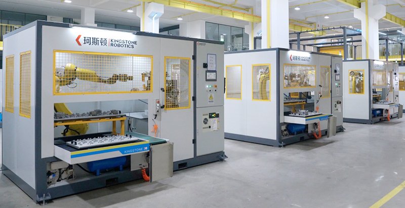
Why Choose Kingstone Robotic Grinding?
- Adhering to independent innovation, Kingstone possesses core technologies and independent intellectual property rights, including an automatic constant pressure system, multi-functional automatic fixtures, composite polishing wheels, and a complete software system suite.
- Offering a turnkey solution from A to Z, even beginners with no prior experience can start a grinding and polishing business and operate a factory.