Description
Robotic Buffing for Extruder Screws
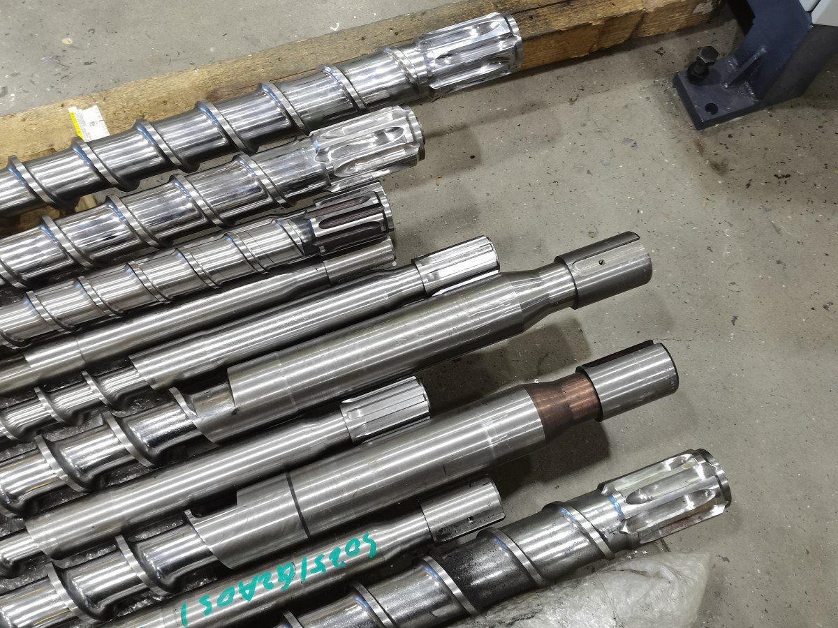
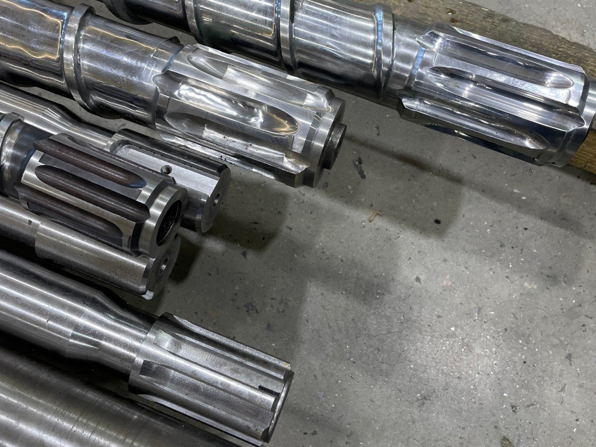
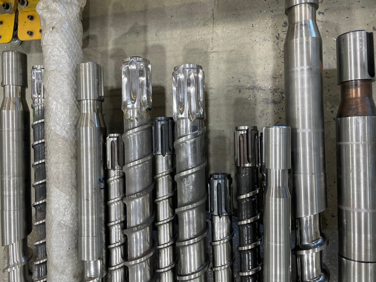
An extruder screw is not a plain round shaft. Its helical flights, root surfaces, transitions and drive end may each have a different finishing requirement. A polishing wheel that works well on an open shaft area may not reach a narrow channel or may contact the flight edge in a different way.
Kingstone develops robotic finishing solutions around the actual screw rather than assigning one machine configuration to every product. The screw drawing, material, length, weight, existing surface condition and specified finish determine how the workpiece is held, which abrasive stations are needed and which areas must remain protected.
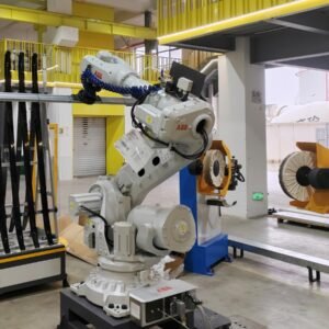
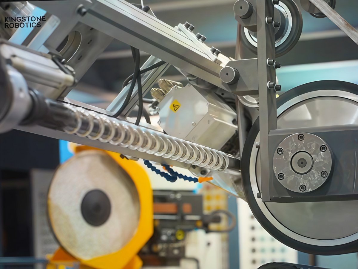
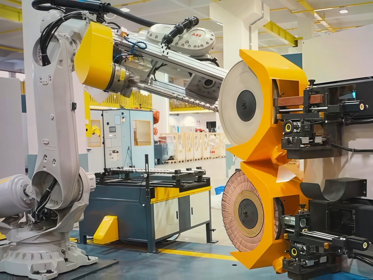
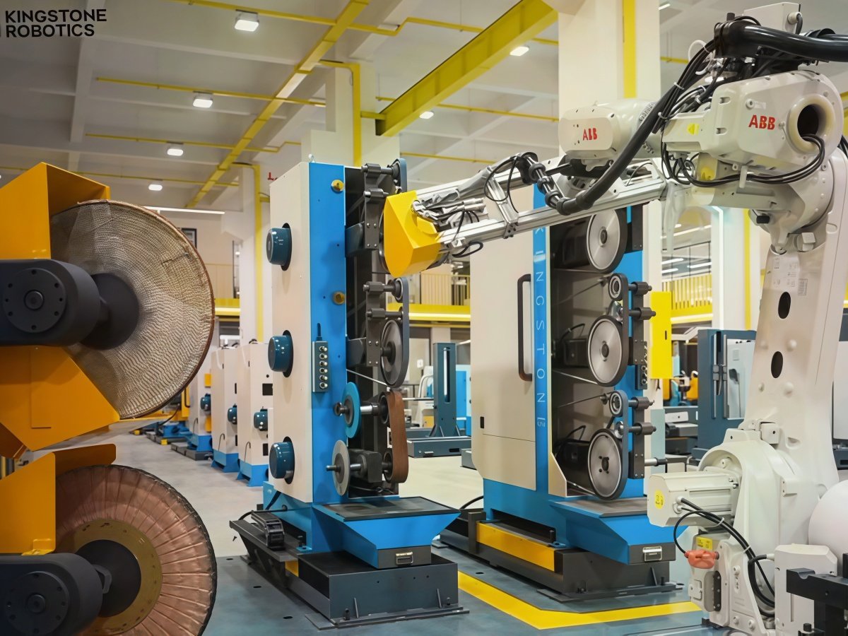
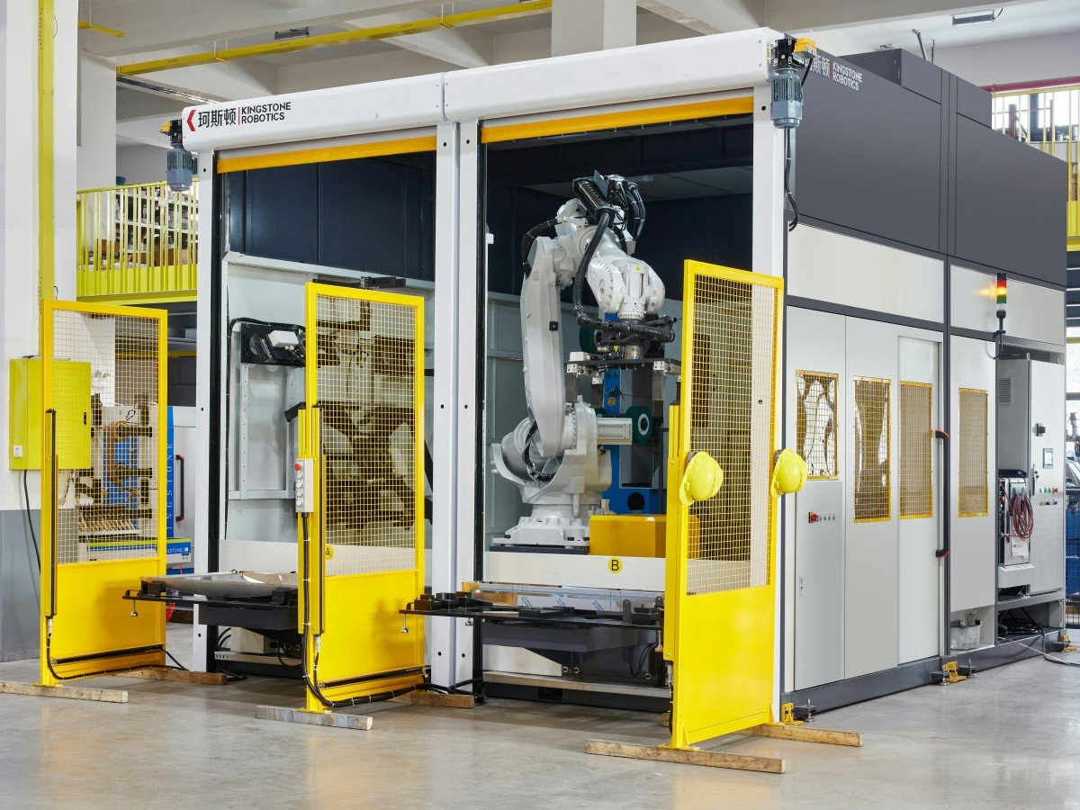
The application photos on this page show a robot presenting a helical screw to finishing stations. The final workstation layout and process for a new project are confirmed through a trial with representative parts.
Which Areas of an Extruder Screw Need Finishing?
The work should begin with a marked drawing or clear photos of the screw. Depending on the part specification, the requested zones may include accessible flight faces, the root between flights, transitions to the shaft or selected cylindrical surfaces. Each zone should be reviewed separately for tool access, starting condition and acceptance criteria.
Some features need protection. Flight outside diameter, bearing fits, drive connections, coated areas and other dimensionally critical features should not be buffed simply because they are visible. Even a light finishing operation removes some material. The customer’s drawing and finished sample should determine where polishing is permitted and how the result is checked.
Buffing can refine an appropriately prepared surface. It cannot rebuild a worn flight, repair deep damage or replace a dimensional restoration process. If a used screw is being considered, its wear and condition need to be evaluated before a finishing method is proposed.
A Typical Robotic Screw Finishing Process
The exact process is developed from sample testing. A practical evaluation may follow these steps:
1. Review the Incoming Screw
Record the screw material, length, diameter, weight, flight geometry, coatings and areas that must not be processed. Compare several normal production parts when incoming condition varies. Agree on a finished reference and any drawing requirements before selecting abrasives.
2. Establish Stable Workholding
A long or unevenly weighted screw needs a gripping and support method appropriate to its mass, center of gravity and contact forces. In the photographed arrangement, the robot carries the workpiece toward stationary finishing stations. Other screws may be better supported in a fixed or rotating fixture while a tool moves around them. The choice depends on workpiece size, access and the complete finishing sequence; our guide to robot-held workpieces and robot-held tools explains the two layouts.
3. Prepare the Surface if Needed
If machining marks or other defects exceed what a buffing wheel can reasonably remove, a separate abrasive preparation step may be required. Belt sanding, flap-wheel finishing and buffing have different roles. No screw should be assumed to need every stage, and an aggressive first step should not be used on protected or closely toleranced surfaces without validation.
4. Buff the Specified Areas
The robot or tool follows a defined path while the abrasive type, contact method, speed and number of passes are tuned to the screw geometry. Access to narrow flight channels must be verified with the full tool, not judged from the screw drawing alone. As wheels wear, the team also needs a repeatable way to maintain the accepted surface result.
5. Inspect the Result
Compare the finished part with the agreed reference. Check for missed zones, remaining scratches, uneven transitions and unwanted rounding at flight edges. Where specified, measure surface roughness and critical dimensions at agreed locations. Appearance alone cannot confirm that a flight outside diameter or fit remains within tolerance.
6. Validate the Production Cycle
Repeat the trial with representative parts, then include loading, gripping, finishing, inspection, consumable changes and unloading in the cycle estimate. For a more detailed method, see our guide to robotic polishing cycle time and production capacity.
Workstation Configuration Depends on the Screw
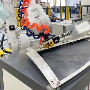
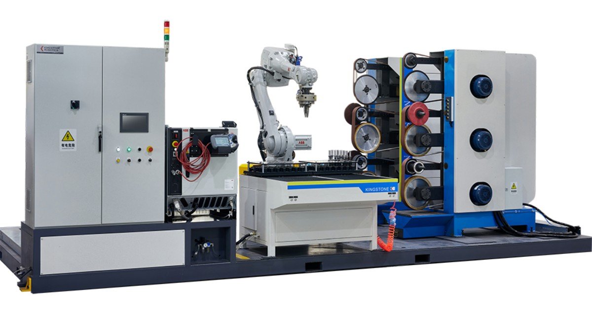
The images show examples of robotic finishing equipment. They should not be read as a single fixed bill of materials for every extruder screw. Possible elements include a robot, a purpose-designed gripper or support fixture, abrasive-belt or wheel stations, a workpiece loading arrangement, safety guarding and dust extraction. An enclosure can be considered when the process and workshop conditions call for it.
| Evaluation item | What determines the final selection |
|---|---|
| Workpiece range | Actual screw length, diameter, weight, center of gravity and variant mix |
| Areas to process | Marked flight, root, transition or shaft zones and their tool access |
| Finishing stages | Incoming condition and the accepted final surface |
| Gripper or fixture | Stable locating and support without marking protected surfaces |
| Abrasive stations | Verified abrasive type, wheel or belt access and required number of steps |
| Guarding and extraction | Cell layout, dust generation, maintenance access and site requirements |
| Inspection | Approved sample, visual criteria and specified roughness or dimensions |
| Output | Cycle confirmed on representative parts, including handling and recurring stops |
The photographed open station and enclosed workstation are configuration examples. They do not establish that both arrangements were used for the same screw or that every function shown is standard on this product.
What Should You Send for a Feasibility Review?
For an initial proposal, please provide:
- A drawing or 3D model with overall length, diameter and flight geometry.
- Material, coating or surface-treatment information, if applicable.
- Clear photos marking areas to finish and areas to protect.
- Current machining or finishing steps and the starting surface condition.
- An accepted finished sample or written surface requirements.
- Workpiece weight, product variants and the required output per shift.
- Several representative raw screws if sample testing is needed.
This information allows the team to assess tool access, workholding, the likely process stages and whether the target finish can be validated without affecting critical geometry.
Frequently Asked Questions
Can a robot buff between the screw flights?
It depends on the pitch, channel depth, flight profile and size of the selected abrasive tool. An accessible area on a drawing may still be blocked by the wheel body or tool mount. A trial with the actual screw is needed to confirm which zones can be finished.
Does buffing change the screw dimensions?
Buffing generally removes less material than heavy grinding, but it is still a material-removal process. Critical flight diameters and fits should be identified and protected or measured according to the customer’s drawing and acceptance criteria.
Is belt grinding always required before buffing?
No. A previously prepared screw may need only a finishing stage, while a screw with more visible machining marks may need additional preparation. The abrasive sequence is selected from the starting surface and target result.
Can one cell process screws of different lengths or profiles?
Possibly, with suitable gripping, supports, tool access and separate validated programs. Changes in length, weight or flight geometry can affect robot loading and cycle time, so each product family needs to be checked.
Can this machine restore a worn extruder screw?
Buffing can address selected surface-finishing needs, but it does not replace missing metal or restore a worn flight diameter. A used screw should first be inspected for wear and damage; any rebuilding work requires a separate repair assessment.
Discuss Your Extruder Screw Finishing Project
Kingstone can review your workpiece and target surface, plan a suitable robotic buffing configuration and test the process on representative samples. Contact our team with your drawings, photos and production requirements to discuss the next step.