Description
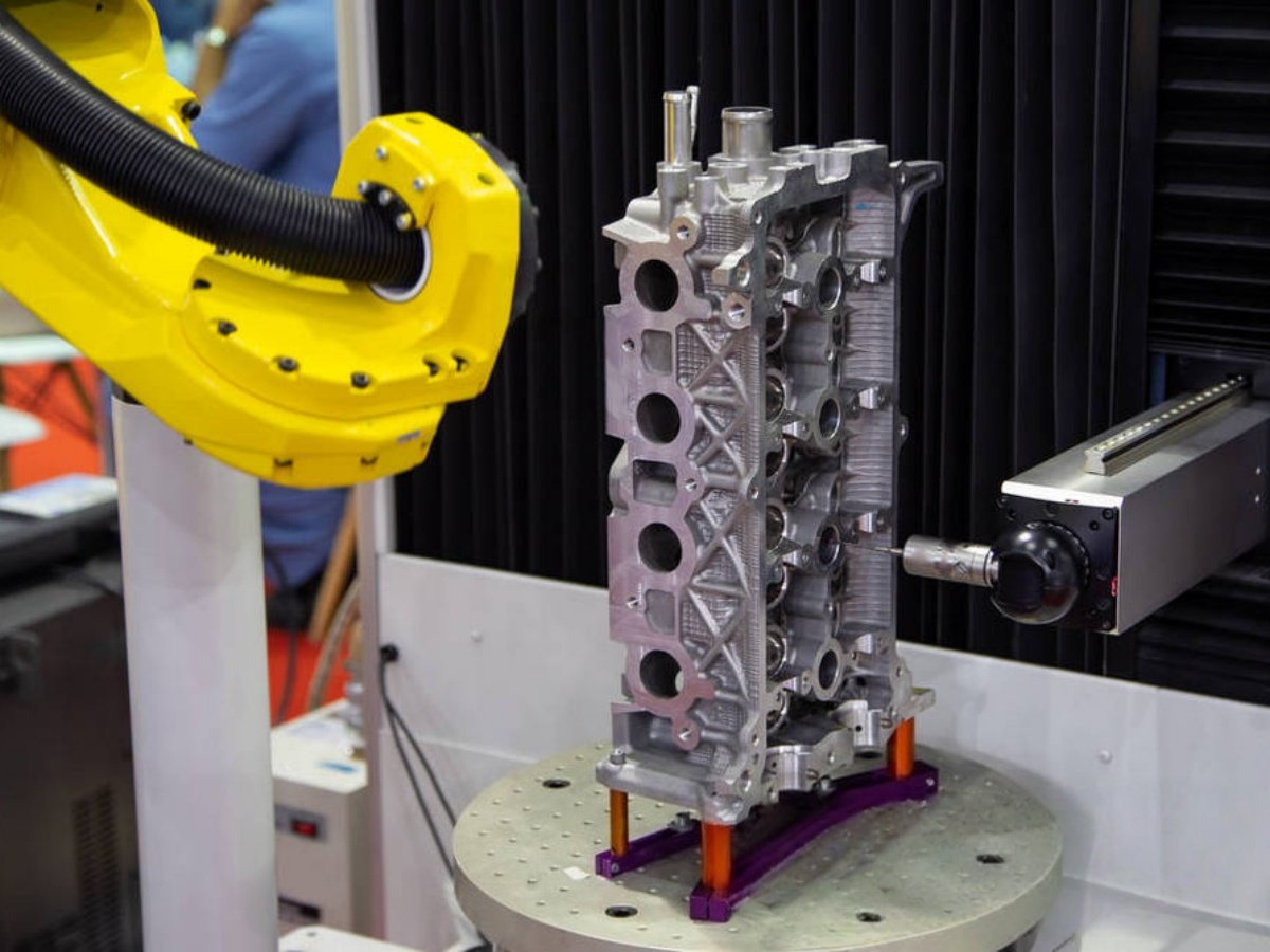
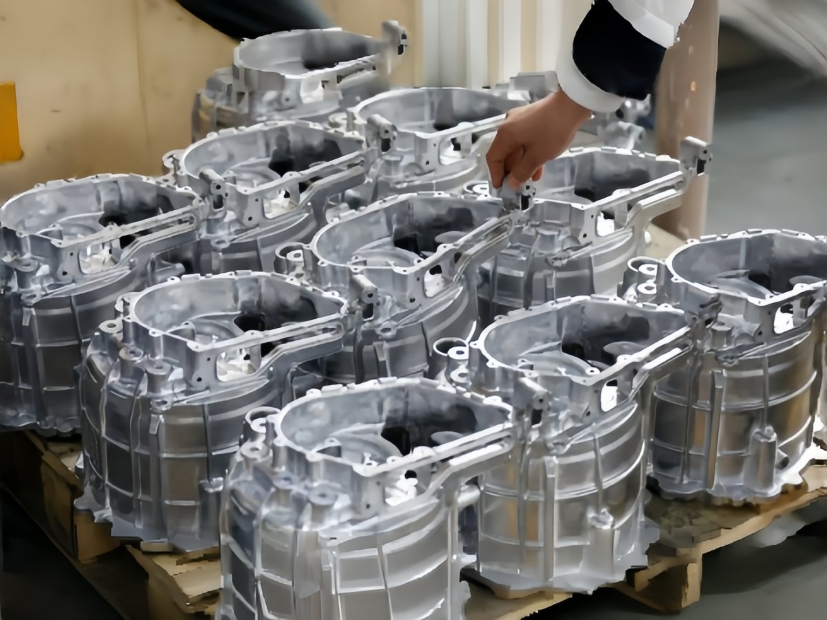
Engine housings combine outer walls, ribs, flanges, openings and functional surfaces in a compact shape. The deburring task changes with the casting method and the manufacturing stage. Flash remaining after casting, a local parting line and a burr created by machining should each be identified before a robotic process is selected.
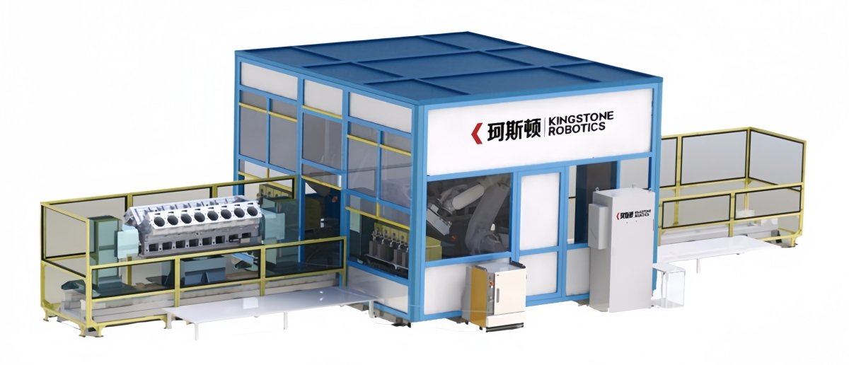
Kingstone develops the application around the surfaces marked on the housing drawing. The process review separates the areas where material must be removed from sealing faces, locating features, machined bores and other areas whose geometry must be preserved.
Map the burrs and access requirements
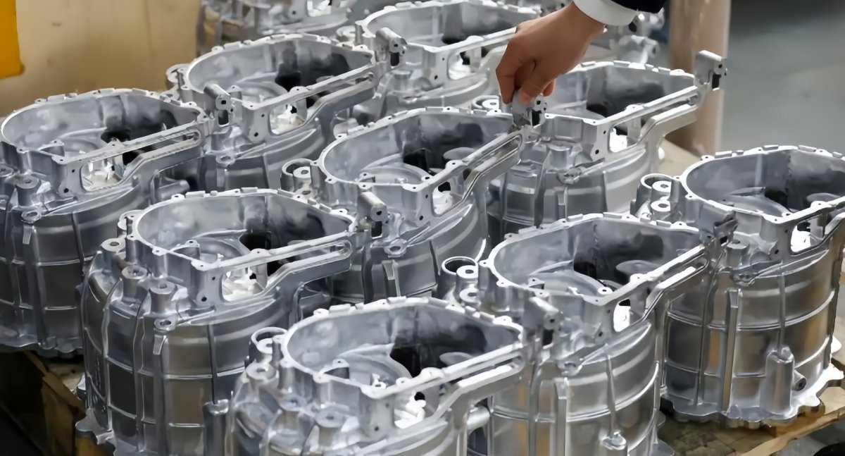
Provide close photographs and, where practical, representative parts showing the expected range of burr conditions. Mark the origin of each burr and the acceptable finished edge. The tool needs access to the complete edge without contacting neighboring walls or the fixture.
Outer edges and open flange contours may be accessible to a robot tool, while a recessed pocket or internal passage may require a specialized method or a separate operation. The application review records these access limits before the proposed scope is finalized.
Protect sealing and machined features
The fixture should locate the housing from repeatable features and resist movement under the expected process force. Contact points and clamping loads are chosen to suit the housing geometry, particularly where thin walls or finished surfaces are involved.
Process paths, tool size and approach direction are planned around protected features. Trial inspection should check that the required burr is removed while the neighboring surface and edge shape remain acceptable.
Choose the tool for each removal task
| Task to evaluate | Process consideration |
| External casting flash or parting line | Incoming stock variation, access and permitted material removal |
| Open edge or flange burr | Tool approach, edge geometry and adjacent sealing surfaces |
| Burr after machining | Burr direction, local access and finished feature protection |
| Recessed or internal feature | Reach, visibility, debris removal and suitability of another process |
Abrasive tools, rotary cutters or other deburring tools are selected for the specific housing material and feature. Tool compliance, force control, sensing or tool change equipment can be included when the process assessment supports them.
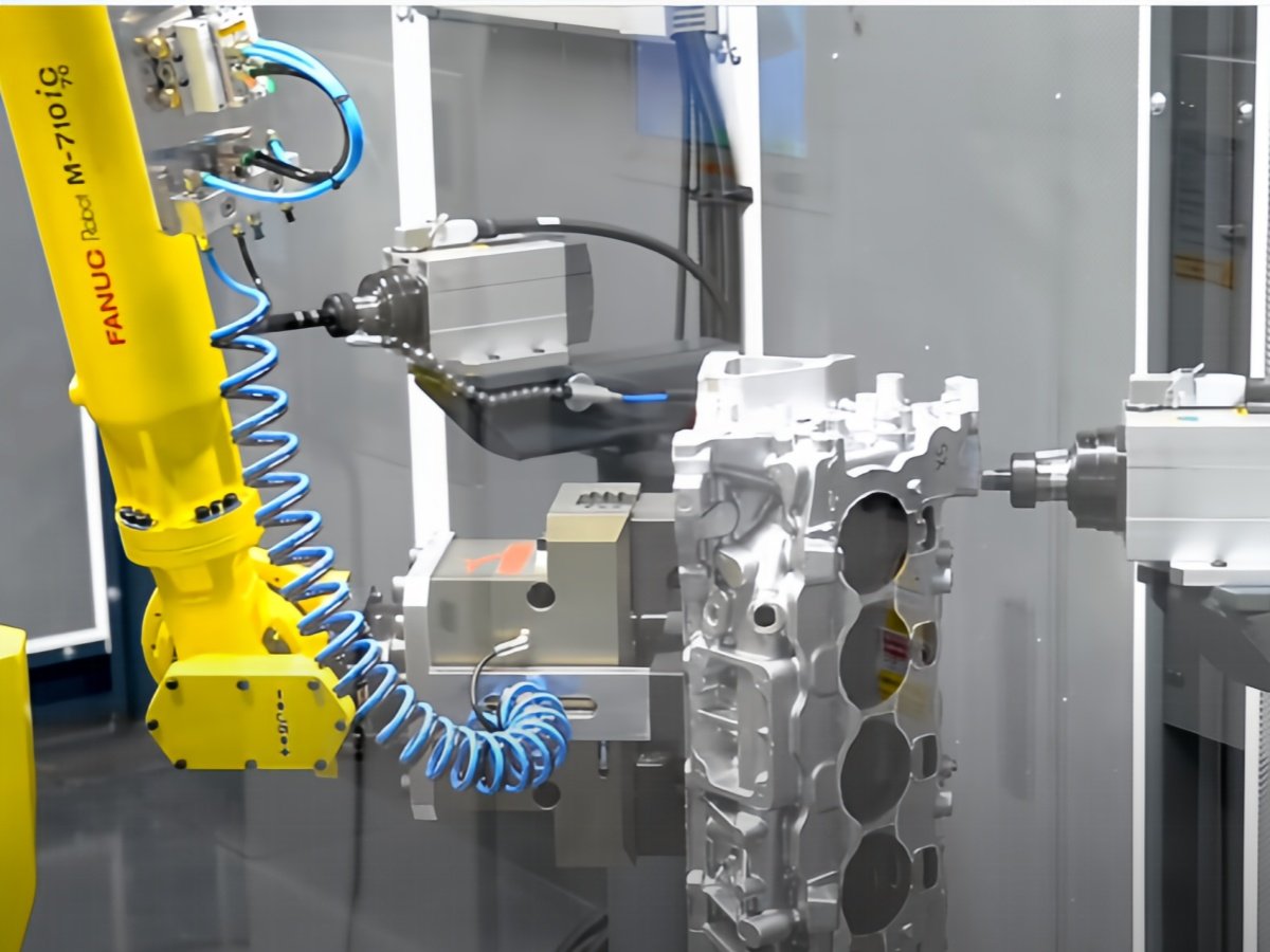
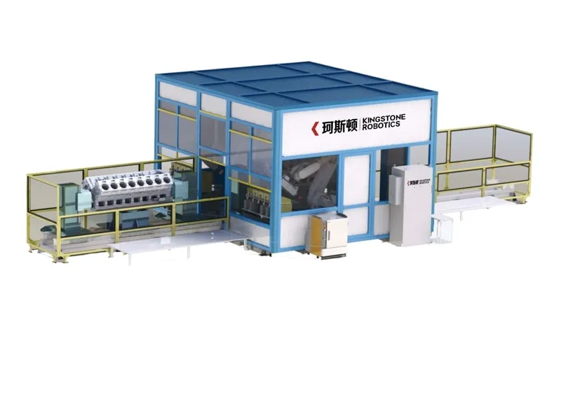
Plan the work cell sequence
- Load the housing into the designated fixture and confirm location.
- Select the correct program for the part reference.
- Process the agreed external contours and accessible edges.
- Reposition the housing or change tools where needed.
- Remove loose process debris as specified and inspect the critical areas.
- Unload the housing for the next manufacturing operation.
Cleaning and technical cleanliness requirements are defined with the customer. A deburring operation alone does not establish the final cleanliness of an assembled engine component; the complete production route and inspection method must address retained chips and abrasive residue.
Validate the result with production parts
Trials should represent the normal variation in the incoming housing. Agree on residual burr limits, permitted edge break, protected dimensions and the inspection method. Use consistent measurement locations when comparing the manual and robotic processes.
Capacity is evaluated for the complete cycle and the intended mix of part numbers. The estimate should include handling, fixture operation, tool changes, cleaning and planned changeovers.
Explore our robotic deburring systems and automotive finishing applications. For the separate requirements of larger axle components, see drive axle grinding and deburring.
Frequently asked questions
Can one cell handle different housing variants?
Compatible housings may share a cell using dedicated programs and workholding. Each variant is checked for access, location, load conditions and the intended inspection requirements.
Can the system deburr internal passages?
Internal access is assessed feature by feature. Tool reach and debris removal can limit robotic processing, so a separate method may be proposed for inaccessible areas.
Can sealing faces be preserved?
Sealing faces and other protected features are identified on the drawing and included in the path planning and trial inspection. Their acceptance limits must be agreed for the application.
Discuss your engine housing
Send the housing drawing and burr photographs with the material, part weight, required output and inspection criteria for an application review.