Robotic deburring of complex metal parts starts with a practical question: can the selected tool reach every required edge in a usable working position? A housing, bracket or valve body may have open outside edges alongside recessed features that need a different approach.
Tool access affects the cutter, fixture, robot motion and number of setups. Reviewing it before choosing a robotic deburring cell helps define which operations can be included and which areas need a separate process.
What Tool Access Means in Robotic Deburring
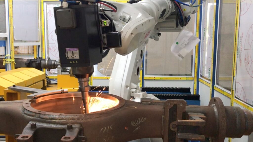
Tool access includes the complete tool assembly and its movement around the workpiece. The cutting edge needs a suitable contact position, while the spindle body, holder, robot wrist and connected services need enough clearance throughout the movement.
A useful review follows the full sequence: approach the edge, establish contact, process the required length, then withdraw. Reaching one point on a drawing does not establish that the whole operation is practical.
Seven Checks Before Selecting a Deburring Cell
1. Identify the Exact Edges and Removal Requirements
Mark the areas to deburr on a drawing or clear photographs. Separate machining burrs, casting flash and parting lines because their removal requirements can differ. Include close views that show the burr location and typical incoming condition.
Specify the result for each area. A sharp edge that needs a controlled edge break has a different acceptance requirement from a raised casting seam that must be blended into the surrounding profile. Also mark threads, sealing faces and other features that must remain untouched.
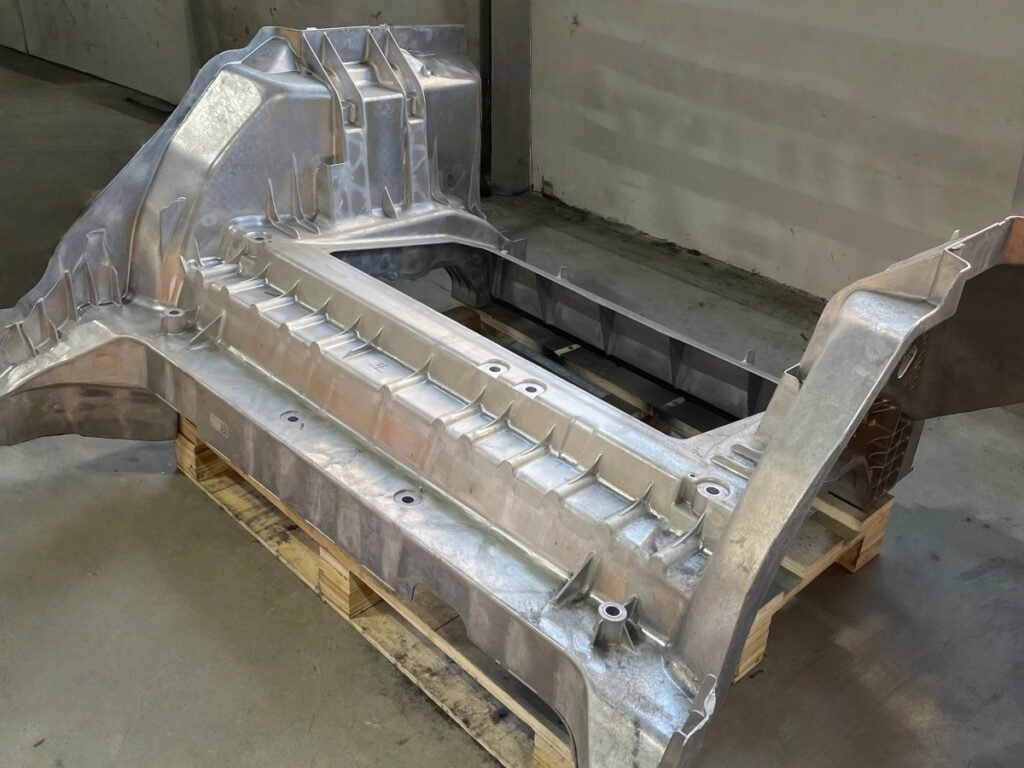
2. Check Clearance Around the Complete Tool
Compare the working diameter and usable reach with the opening, recess depth and surrounding walls. Include the collet, spindle housing and any compliance device in the clearance review. A small cutter can enter an opening while the larger tool body still limits the working depth.
A longer extension changes tool stiffness and must stay within the tool manufacturer’s permitted arrangement. Where clearance is restricted, evaluate another tool shape, approach direction or separate operation rather than assuming an extension will solve the problem.
3. Review the Approach and Withdrawal Paths
The robot must move into and out of the processing area as well as follow the edge. Check the wrist, arm, tool holder and cable or hose routing against the workpiece, fixture and nearby equipment throughout these movements.
Offline simulation can help review reach, orientation and collision risks using a model of the complete cell. Physical commissioning must still confirm the actual setup, tool locations and movement clearances.
4. Keep Fixture Elements Clear of the Processing Area
A clamp beside a burr may prevent the tool from maintaining its working angle. Locators and supports can also obstruct the final section of a path. Review the fixture together with every tool needed for the part.
For example, a housing with burrs around several openings may need a different clamp position or a second setup to expose all specified edges. Any added setup introduces another locating step and handling time. Our guide to robotic polishing fixture design explains the related workholding checks.
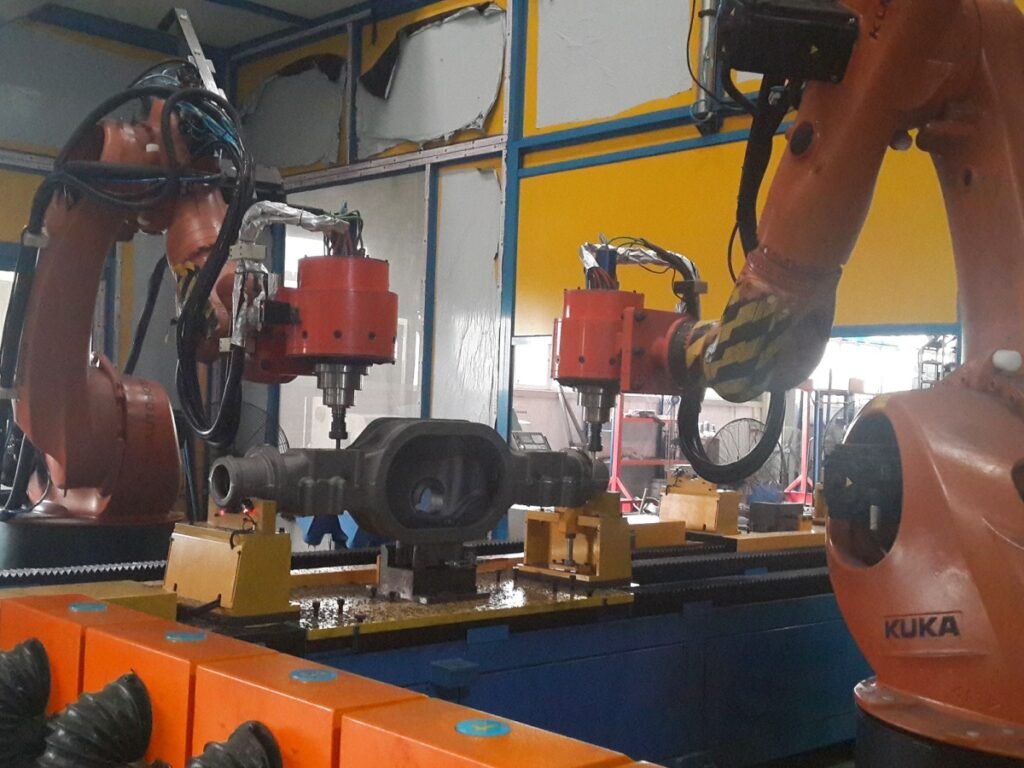
5. Choose How the Part Will Be Presented to the Tool
Some components can be held by the robot and moved against a stationary tool. Others are better reviewed in a fixed fixture with the robot carrying the deburring tool. A positioner may provide additional access where changing the part orientation is practical.
Compare these arrangements using the actual part and tooling. A positioner adds equipment, motion and locating requirements that belong in the proposal. Our robot-held part versus robot-held tool guide covers the main configuration choices.
6. Confirm the Contact Method for Each Edge
Tool orientation, feed and contact conditions affect how material is removed. A tool suitable for an exposed outer edge may require a different arrangement for a recessed corner or a transition between surfaces.
Compliance or force control can help manage defined variation within the selected device’s working range. It cannot create clearance where the tool body is blocked. Confirm the contact method with the proposed tool and representative parts, including the expected variation in burr size and part location.
7. Inspect Every Specified Area After Testing
Check accessible outer edges and the difficult recessed areas against the same agreed requirements. Confirm that burrs have been removed without unacceptable edge rounding, gouges or damage to adjacent features.
Choose an inspection method suited to each location. A deep recess may need a different viewing or measurement method from an open flange. Record any area excluded from the robotic process, and include the time for reorientation and additional setups when reviewing the complete cycle.
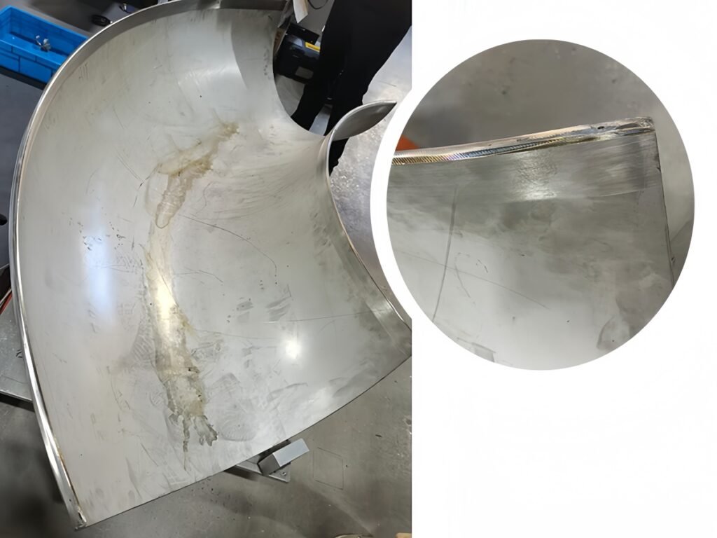
Information to Send for a Tool Access Review
An initial review is more useful when the required areas are clearly identified. Prepare the following information:
- A drawing or 3D model with the edges to process marked.
- Material, overall dimensions and part weight.
- Close photographs of the burrs, flash or parting lines.
- Recess depths, opening sizes and restricted areas.
- Permitted clamping locations and surfaces to protect.
- Required edge condition, inspection method and target output.
Representative raw parts are important when the project moves to testing. Where available, include a finished reference part. Agree the acceptance requirements before assessing the trial result; our surface finish acceptance guide explains how to document visual and measured requirements.
When Several Tools or Setups Are Needed
A complex part may combine broad areas that need grinding with local edges that need deburring. Each operation needs its own tool access check. The proposal should identify the tools, working positions and handling steps for the complete part.
An integrated robotic grinding and deburring cell can be evaluated when several operations belong in one system. Tool changing, part positioning and additional stations are application choices that need to be defined in the project scope.
Frequently Asked Questions
Can a robot deburr every internal edge
Feasibility depends on the opening, depth, tool geometry and required result. Some internal features are suitable for a selected robotic tool; others require another process. Review the actual geometry and confirm difficult areas through testing.
Does a larger robot solve restricted tool access
A larger robot may address a reach or load requirement. Access inside a recess still depends on the tool dimensions, working angle and surrounding geometry. Check both the robot and the tool before selecting the cell.
Can one tool remove all burrs on a casting
Some parts can use one tool, while mixed burr types or restricted features may require several. The choice depends on the removal task, access, tool limits and accepted edge condition. Sample testing should establish the proposed sequence.
Discuss Your Complex Part Deburring Project
Kingstone Robotics develops grinding and deburring systems around the specified workpiece and process. Contact our team with your drawings, marked processing areas and incoming-part photographs to discuss tool access, workholding and the testing needed for your application.
Email: info@automatedpolish.com
WhatsApp: +86 151 5987 5082